Fireplace installation – Desa CD36TN-M User Manual
Page 19
www.desatech.com
118531-01A
19
4. Swing the junction box out and slip retaining
flange out through the slot in outer cabinet.
5. Remove two screws and outer cover on the
left side of the outer cabinet.
6. Reinsert junction box retaining flange through
slot now on the left side and swing screw
mounting tab back through notch as before.
7. Slide the junction box down till mounting tab
holes line up and replace the inner retaining
screw.
8. With junction box cover removed, pull the end
of 3-wire Romex supply line through universal
strain relief bushing on cover (see Figure 26,
page 18).
9. Strip back the outer Romex to about 4" and
connect black, white and green wires accord-
ingly using 3 wire nut connectors.
10. Tuck tailing wires into junction box and
replace junction box cover using 2 remaining
screws.
11. Tighten down strain adjustment on universal
bushing until Romex sheathing is secured.
The electrical connection is now complete.
INSTALLING OPTIONAL BLOWER
ACCESSORIES
NOTICE: If installing blower in
an existing fireplace with gas
connections, shut off gas sup-
ply and disconnect heater from
gas supply. Contact a qualified
service person to do this.
WARNING: If there is a du-
plex electrical outlet installed
in the right side of the bottom
of the fireplace base area, be
sure that the electrical power
to the outlet is turned off before
proceeding with blower instal-
lation. Failure to do this may
result in serious injury.
Model BK Installation
Follow all instructions provided in the blower
accessory kit.
FIREPLACE
INSTALLATION
Continued
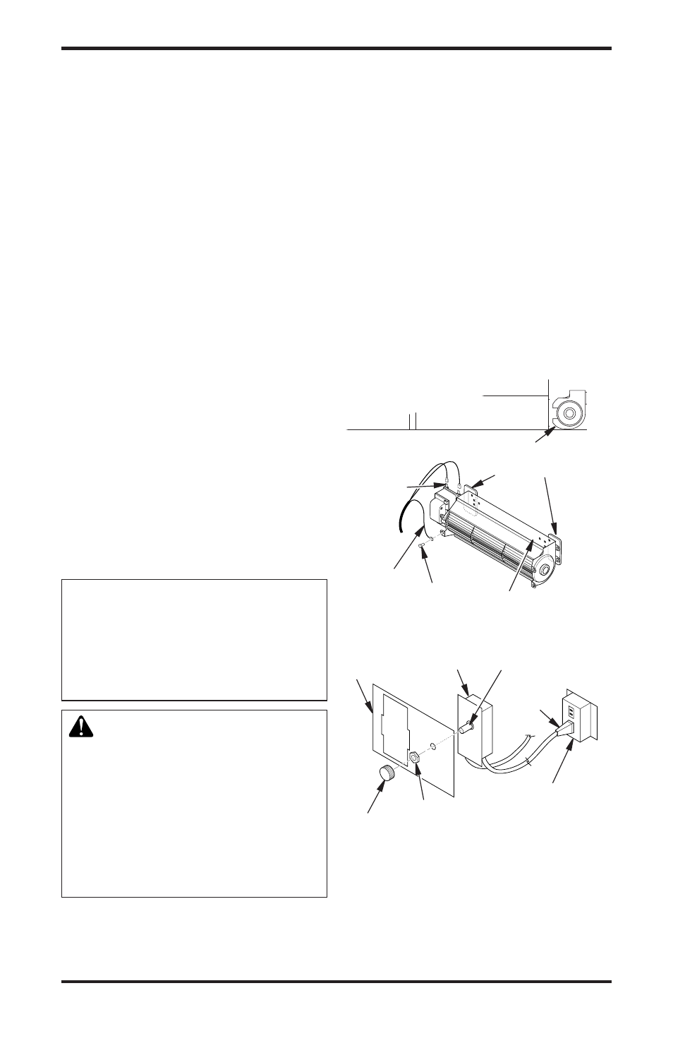
1. Attach power cord to blower motor by firmly
pushing the two female terminals at the end of
power cord onto the two spade terminals on
blower motor (see Figure 27).
2. Attach green ground wire from power cord
to blower housing using screw provided (see
Figure 27). Tighten screws securely.
3. Place blower against lower rear wall of the
firebox outer wrapper with exhaust port di-
rected upward. The blower will fit inside the
back opening and be held in position against
the back wall by magnets (see Figure 27).
4. Be certain that all wire terminals are securely at-
tached to terminals on blower motor and that the
screw retaining the green ground wire is tight.
5. Mount speed control box by placing plastic
control shaft through opening in switch
bracket (see Figure 28).
Blower Location
Side View
Figure 27 - Blower Model BK
Magnetic
Strips
Exhaust Port
Screw
Green
Ground
Wire
Spade
Terminals
Lower Firebox
Cavity
Figure 28 - Attaching Speed Control to
Firebox (Millivolt Models)
Speed Control Control Shaft
Locknut
Control
Knob
Switch
Bracket
Blower
Plug-In
Duplex Outlet
(Located underneath
firebox floor against
lower right outside wall)