Venting installation instructions – Desa CD36TN-M User Manual
Page 13
www.desatech.com
118531-01A
13
H
V
GROUND FLOOR INSTALLATION
Recommended CHVK-58 Corner Horizontal
Vent Kit:
• Installation using cabinet surrounds
• Through the wall using square termination
(up to 24" horizontal pipe)
• Corner installation (Using one 6" vertical sec-
tion, one 90° elbow and a maximum of 24" of
horizontal pipe)
VENTING INSTALLATION
INSTRUCTIONS
Continued
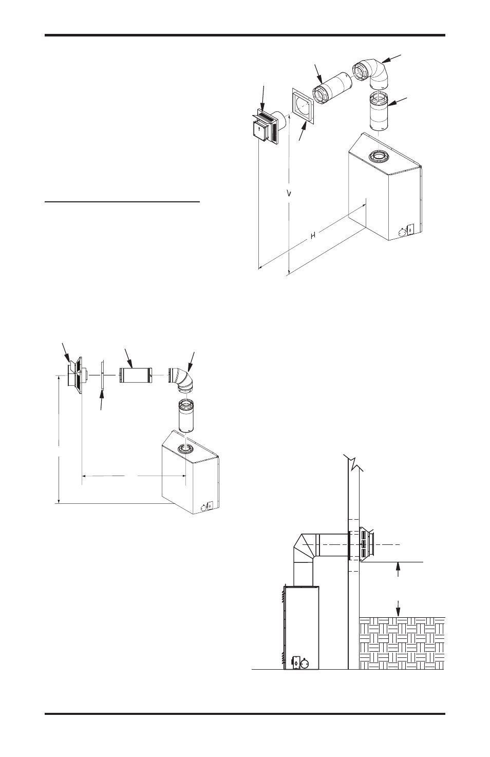
Figure 14 - Horizontal Termination
Configuration For Corner Installation
Using One 90° Elbow
Figure 15 - Horizontal Termination
Configuration with Vertical Rise and One
90° Elbow
Required
Vertical (V)
Vertical (V)
Vertical Pipe
Allowable
Horizontal (H)
51"
"
" Max.
5
1
/
4
" Min.
1'
30" Max.
9
1
/
4
" Min.
'
4" Max.
81
1
/
" Min.
3'
98" Max.
94" Min.
4'
1" Max.
10" Min.
5'
14" Max.
159" Min.
9'
0' Max.
TO
H
Wall
Firestop
Straight/
Adjustable
Pipe 4" Max.
Horizontal
Square
Termination
90°
Elbow
Corner Installation
Vertical (V)
Horizontal (H)
51" Min.
3
1
/
" Max
90° Elbow
Wall
Firestop
Square
Termination
Not to Exceed
(H) Limits
As
Required
for (V),
See Chart
for Pipe
Section
Required
Horizontal Termination Configurations
Figures 14 through 18 show different configura-
tions and alternatives for venting with horizontal
termination. Each figure includes a chart with
critical minimum and maximum dimensions which
MUST be met. IMPORTANT: Remember that a
horizontal run of venting must have a 1/4" rise for
every 12" of run toward the termination.
Figure 16 - Square Termination
Clearance at Ground Floor Installation
1"
Min.