5 dc voltage sources, 6 thermocouples, 7 strain and pressure gages – Sensoray 2518 User Manual
Page 17
Sensoray Model 2518/2519 Ethernet Smart A/D™
14
Sensor Connections
where they are tied together. This circuit eliminates cable
loss effects from both the V+ and V- lines.
5.4.4 Recommended Practice
If sensor field wiring is exposed to electrical noise (i.e.,
the cable run is long or is close to noisy conductors) you
should consider using shielded cable. The cable shield
must be connected only to the S terminal on the TB and
left unconnected at the sensor end of the cable.
The four-wire circuit should be used when accuracy is
critical. This is especially important when making
precision low-resistance value measurements, such as
when using RTDs.
Thermistors have much higher resistance values than
RTDs over most of their operating range. Consequently,
the two-wire circuit may be used if your sensor will be
operating exclusively at high resistance values. However,
if your thermistor will be operating at lower resistance
values, you should consider implementing a three-wire or
four-wire circuit to reduce or eliminate cable-loss errors.
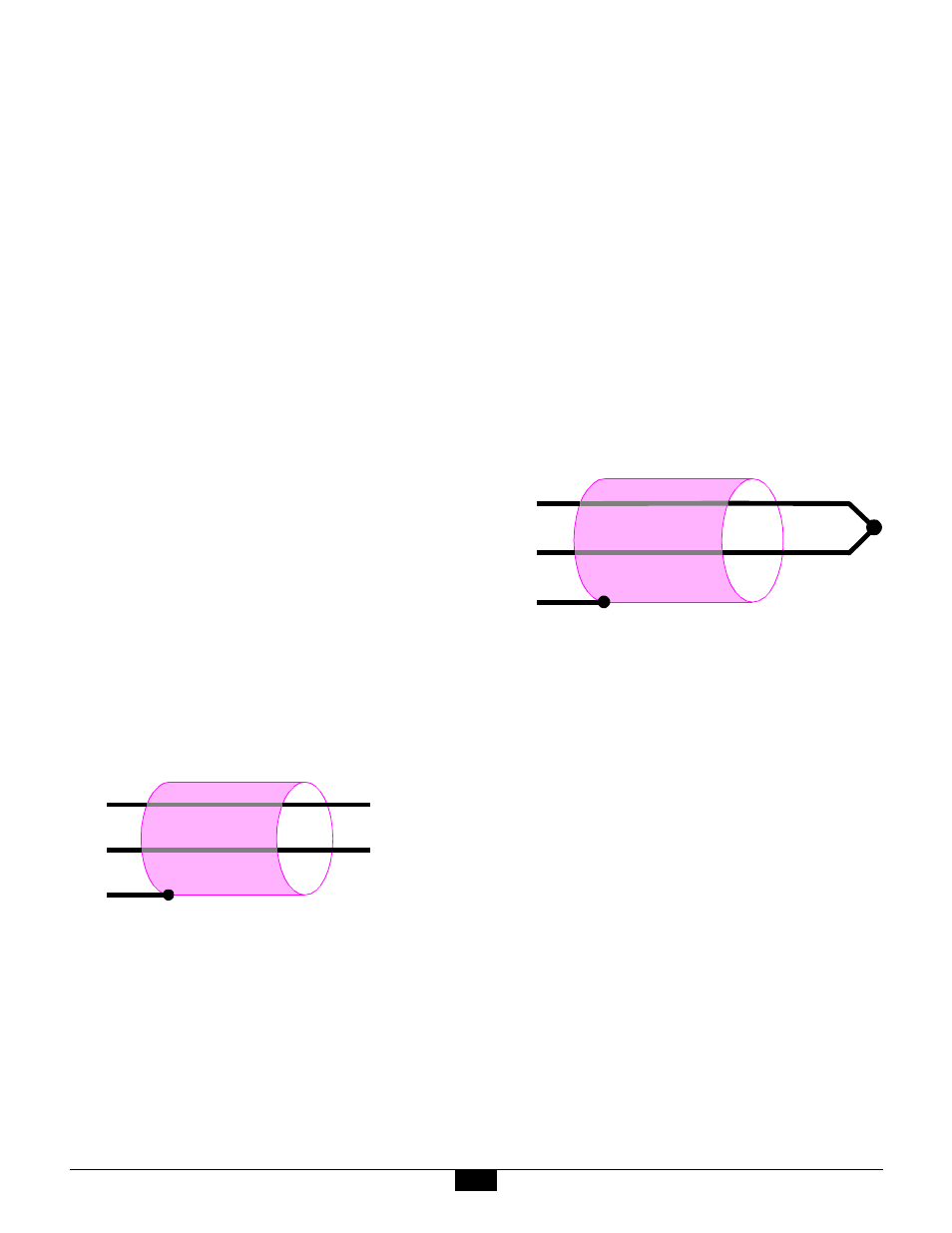
5.5 DC Voltage Sources
DC voltage sources are connected directly to the V+ and
V- terminals. DC voltage sources should never be
connected to the I+ or I- terminals.
Since all voltage input ranges are bipolar, DC voltages
may be connected in either signal polarity. Although the
diagram below shows Voltage+ connected to V+ and
Voltage- connected to V-, there is no reason that Voltage+
must be positive with respect to Voltage-.
Figure 14: DC voltage connection
5.5.1 Recommended Practice
In order to assure accurate DC voltage measurements,
high common-mode voltages (CMV) must not be
permitted to appear on V+ or V-.
If your signal source is isolated (i.e., sourced from a
battery or isolated power supply), you can connect V+ or
V- to either S or the backplane power supply return. This
connection can be implemented as a direct short or can be
made through, for example, a 10K
Ω
resistor. There
should be no significant DC current flowing through this
connection; its purpose is to limit the common-mode
voltage at the sense inputs.
In the case of low source impedance voltage sources,
another way to limit CMV is to install the channel signal
conditioning circuit as described in Section Chapter 4:.
5.6 Thermocouples
Thermocouple (TC) signals are connected directly to the
V+ and V- terminals. TCs should never be connected to
the I+ or I- terminals.
TC wires are color coded to indicate polarity. The red
thermocouple wire is always negative, by convention.
The positive TC wire should always be connected to the
V+ terminal, and the negative wire should always be
connected to the V- terminal.
Figure 15: Thermocouple connection
5.6.1 Recommended Practice
Two TC reference-junction temperature sensors are
located on the model 2509 base board. Because these
reference sensors, as well as the sensor terminal blocks,
have non-zero thermal mass, it is critical that the base
board operate in a stable thermal environment so as to
minimize thermal gradients across the termination
system.
Significant measurement errors can occur if you expose
the base board to thermal transients, such as air flows
from cooling fans or ambient breezes. For best results,
the unit should be located within a protective enclosure
after sensor terminations have been made.
If your TC is ungrounded, always enable the channel
signal conditioning circuit. See “Configuration” on
page 8 for details.
5.7 Strain and Pressure Gages
In a typical strain/pressure gage sensor, four wires are
used to connect the gage to the sensor channel. Two of
the wires supply gage excitation, while the other two
V +
V –
S
Voltage +
Voltage –
V +
V –
S
RED