Sensoray 2518 User Manual
Page 13
Sensoray Model 2518/2519 Ethernet Smart A/D™
10
Configuration
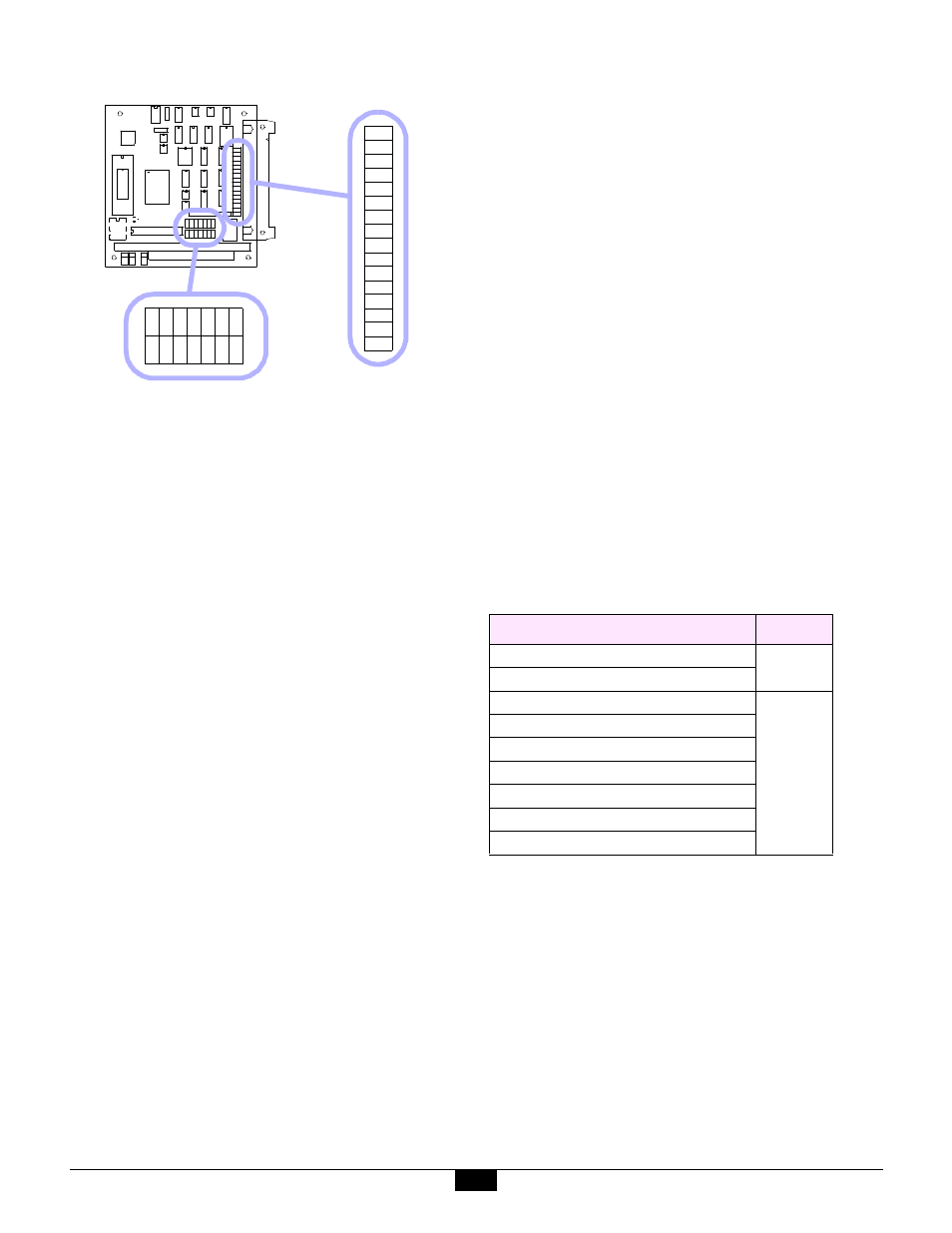
Figure 9: Model 518 programming shunts
4.3.2 Base Address Selection
IRQ and I/O addresses are factory programmed and
should never need to be changed. When installed on a
model 2509 Ethernet base board, model 518 daughter
boards should be configured as follows:
•
Address (E1 to E8). The lower model 518 board,
which is the only model 518 board residing on model
2518, is set to base address 2B0 hex. In the case of
model 2519 only, the upper model 518 board is set to
base address 2B4 hex.
•
Interrupts (IRQ2 to IRQ7). The lower model 518
board is set to generate interrupts on IRQ2, and on
model 2519 only, the upper model 518 board is set to
generate interrupts on IRQ3.
See the model 518 instruction manual for details on how
to configure model 518 interrupt and address options.
4.3.3 Signal Conditioning Circuits
Each of the eight sensor channels on a model 518 Smart
A/D™ board is provided with a signal conditioning
circuit (SCC) which may be inserted into the sense signal
path. This conditioning circuit performs three functions:
q
Common-mode tie-down. This function helps to
prevent the common mode voltage (CMV) from
straying beyond the input CMV range of the Smart
A/D™ measurement section. This function is
required when a sensor channel is driven from an
isolated source, such as a battery, isolated power
supply, or thermocouple.
q
Open-sensor detect. If either of the two sense
signals should become disconnected from the source,
this function forces a differential voltage of 700mV,
minimum, to appear across the sense inputs. This
function is useful when a sensor is used in a control
loop.
q
RF shunt. This function, which shunts RF noise to
ground, is essential when connecting to isolated
sources, such as thermocouples.
4.3.4 Side Effects
The input impedance of a channel’s Sense inputs is
reduced when that channel’s SCC is enabled. See
“General Specifications” on page 26 for details.
Ordinarily, this reduction of input impedance will not be
an issue for thermocouples. In the case of other types of
voltage sources, however, measurement accuracy may be
degraded if such sources have high source impedance.
4.3.5 Recommended Settings
The decision of whether or not to enable a channel SCC
is influenced primarily by the type of sensor to be
interfaced, and, in the case of active sources, whether or
not the source is ground-referenced.
Listed below are recommendations for enabling vs.
disabling the SCC:
4.3.6 Shunt Mapping
Shunts E9 through E24 are used to control the enabling
of SCCs for all sensor channels. Each channel is
affiliated with two shunts. To enable a channel’s SCC,
you must install both of the affiliated shunts. Similarly,
to disable the SCC, you must remove both shunts.
E
1
E
2
E
3
E
4
E
5
E
6
E
7
E
8
IR
Q
2
IR
Q
7
IR
Q
6
IR
Q
5
IR
Q
4
IR
Q
3
E19
E20
E17
E18
E23
E24
E21
E22
E11
E12
E9
E10
E15
E16
E13
E14
Table 3: Recommended signal conditioner settings
Sensor Type
SCC
Ungrounded Thermocouple
Enabled
Isolated DC Voltage Source
Grounded Thermocouple
Disabled
Ground-referenced DC Voltage Source
4-to-20 mA loop
Resistor
RTD
Strain/Pressure Gage
Thermistor