3 model 518 smart a/d™ boards – Sensoray 2518 User Manual
Page 12
Sensoray Model 2518/2519 Ethernet Smart A/D™
9
Configuration
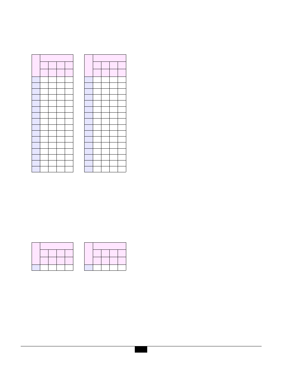
Table 1 illustrates how to install shunts for all of the
possible values of the field-programmable IP address
byte.
l
indicates shunt is installed
m
indicates shunt is removed.
Example:
The desired IP address is 10.0.0.42. The
programmable byte value, 42, which is expressed in
decimal, must first be converted to hexadecimal;
decimal 42 = hex 2A. Now, using Table 1, it can be
seen that shunts must be installed as follows:
On revision A-D boards, the installed shunts are A8,
A7, A5, A3 and A1. On revision E boards, shunts must
be installed on column 0, rows 7, 6, 4, 2 and 0
4.2.3 Default IP Address
Models 2518 and 2519 are factory programmed to set the
unit’s IP address to 10.0.0.127.
4.2.4 Choosing an IP Address
On most networks, Ethernet IP addresses can be assigned
arbitrarily so long as the assigned address does not
conflict with another host on the same LAN.
In rare cases, addresses in the range 10.0.0.X will not
work. In such cases, Sensoray can provide custom
programming of the units to provide alternative fixed IP
address ranges. Contact [email protected] for details.
4.3 Model 518 Smart A/D™ Boards
Model 518 Smart A/D™ daughter boards have two
groups of programming shunts. One group is used to set
the board base I/O address, and the other group is used to
enable channel signal conditioning circuits.
Model 2518 has one Smart A/D™ daughter board which
interfaces to Smart A/D™ sensor channels 0 to 7. Model
2519 has two Smart A/D™ boards. The lower Smart
A/D™ board interfaces to channels 0 to 7, while the
upper board interfaces to channels 8 to 15.
Option shunts are easily accessed on the uppermost
Smart A/D™ board. If option shunts must be modified
on the lower Smart A/D™ board of a model 2519, you
will need to remove the upper Smart A/D™ board to gain
access to shunts on the lower board. This is
accomplished by removing the four screws from the
corners of the upper board, then carefully unplugging the
upper board from the lower board. After the shunts have
been set on the lower board, plug the upper board back
onto the lower board and reinstall the four screws.
4.3.1 Shunt Locations
The following diagram shows the locations of hardware
programming shunts on the model 518 Smart A/D™
board.
Table 1: IP Address programming shunts
V
a
lu
e
High Nibble
V
a
lu
e
Low Nibble
A8 A7 A6 A5
A4 A3 A2 A1
7
6
5
4
3
2
1
0
0
l l l l
0
l l l l
1
l l l m
1
l l l m
2
l l m l
2
l l m l
3
l l m m
3
l l m m
4
l m l l
4
l m l l
5
l m l m
5
l m l m
6
l m m l
6
l m m l
7
l m m m
7
l m m m
8
m l l l
8
m l l l
9
m l l m
9
m l l m
A
m l m l
A
m l m l
B
m l m m
B
m l m m
C
m m l l
C
m m l l
D
m m l m
D
m m l m
E
m m m l
E
m m m l
F
m m m m
F
m m m m
Table 2: Example - Select IP Address 10.0.0.42
V
a
lu
e
High Nibble
V
a
lu
e
Low Nibble
A8 A7 A6 A5
A4 A3 A2 A1
7
6
5
4
3
2
1
0
2
l l m l
A
m l m l