4 counter setup registers – Sensoray 626 User Manual
Page 20
Sensoray Model 626 Instruction Manual
18
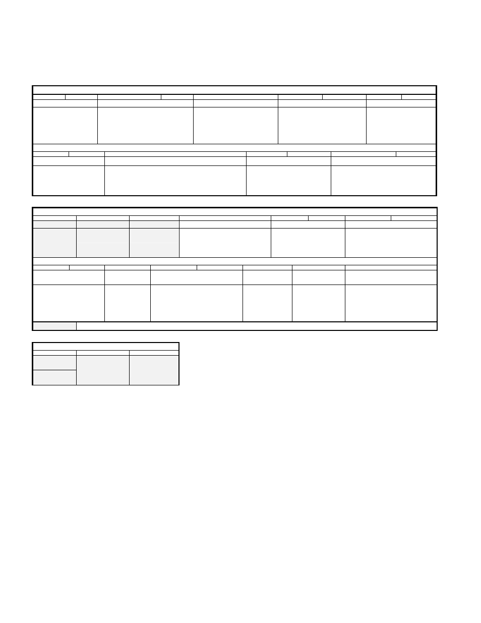
10.4 Counter Setup Registers
Table 15 CR0A 00 (hex) Read/Write
Bit 15
Bit 14
Bit 13
Bit 12
Bit 11
Bit 10
Bit 9
Bit 8
Bit 7
Counter B index source Counter B source
Counter A Index edge selection Counter A pre-load trigger source Counter A multiplier
00=Encoder
01=Digital inputs
10= Controlled by bit 1
of CR1B
11= Index disabled
00=Encoder
01=Digital inputs
10=Up Count with System clock
11=Down count with System clock
(10 & 11 gated by bit 1 of CR1B)
0=Positive
1=Negative
(Also used for software control
of Counter A Index, 1=index)
00=Counter A index pulse
01=Counter A overflow
10=Disabled
11=Disabled
00=4x
01=2x
10=1x
11=Channel A is direction
Index is count pulse
Bit 6
Bit 5
Bit 4
Bit 3
Bit 2
Bit 1
Bit 0
Counter A interrupt source Counter A source edge selection
Counter A Index source
Counter A source
00=None
01=Overflow only
10=Index only
11=Index & Overflow
0=Positive
1=Negative
Also software control of Counter A count pulse.
1=enable when running with the system clock.
00=Encoder
01=Digital inputs
10= Controlled by CR1A bit11
11= Index disabled
00=Encoder
01=Digital inputs
10= System clock up (gated by bit4)
11= System clock down (gated by bit4)
Table 16 CR0B 02 (hex) Read/Write
Bit 15
Bit 14
Bit 13
Bit 12
Bit 11
Bit 10
Bit 9
Bit 8
Clear Interrupt Select Interrupt B Select interrupt A Counter A Enable
Counter B interrupt source Latch source
1=Clear
Used with
bit 13 or 14
1=Selected
Used with bit 15
1=Selected
Used with bit 15
0=Enabled
1=Only enabled if index A is high
00=None
01=Overflow only
10=Index only
11=Index & Overflow
00=Depends on latch read address
01=A’s index latches A
10=B’s index latches B
11=Counter A overflow captures B
Bit 7
Bit 6
Bit 5
Bit 4
Bit 3
Bit 2
Bit 1
Bit 0
Counter B pre-load trigger
source
Clear Counter B Counter B multiplier
Counter B Enable Counter B index
edge selection
Counter B source edge selection
00=Counter B index pulse
01=Counter B overflow
10= Counter A overflow
11=Disabled
1=Counter A
overflow clears
Counter B
0=Not Cleared
00=4x
01=2x
10=1x
11=Channel A is direction
Counter A overflow is count pulse
0=Enabled
1=Only enabled if
index B is high
0=Positive
1=Negative
(Also software
control of Counter
B Index, 1=index)
0=Positive
1=Negative
Also software control of Counter B
count pulse. 1=enable when
running with the system clock.
The grayed bits read back different information to that which was written to them. (See “Table 17 CR0B 02 (hex) Read” below).
Table 17 CR0B 02 (hex) Read
Bit 15
Bit 14
Bit 13
Counter B
Direction
0=Down
1=Up
1=Counter A
overflow routed to
digital output
1=Counter B
overflow routed
to digital output
In the following examples groups of bits will be referred to using their name and set to a binary value.
For example ‘Counter B Multiplier’=10 means bit 4 =1 and bit 3=0.
‘X’ is used to show the value of a bit in one of the counter registers that is not important to the example
being discussed. This is not to say it should be ignored. The value of these bits will depend on other
functions being used and writing to any bit in the configuration example will always have an effect.
Some bits have dual functions depending on the present settings of other bits.
Many of the counter examples will only deal with counter 0A. Unless otherwise stated the function
being discussed can also be applied to counter 0B. The correct register & bit/s just need to be used by
looking at the applicable tables. Counters 1A, 1B, 2A & 2B will function in the same way just controlled
using different register addresses.
Do not be confused by the naming of registers CR0A & CR0B. They are simply the A & B parts of the
single register CR0 (Counter Register 0) and do not refer specifically to counter A and counter B.
Counters 1 & 2 have the same register layout but with
different Read/Write addresses.