Connections & settings, Leak detection board, Tb8 – power – RLE LDZ4 User Manual
Page 9: Chapter 2: connections & settings, Figure 2-1: ldz4 leak detection board
User Guide: LDZ4
Chapter 2: Connections & Settings
www.rletech.com 970.484.6510
3
CHAPTER 2: CONNECTIONS & SETTINGS
2-1
LEAK DETECTION BOARD
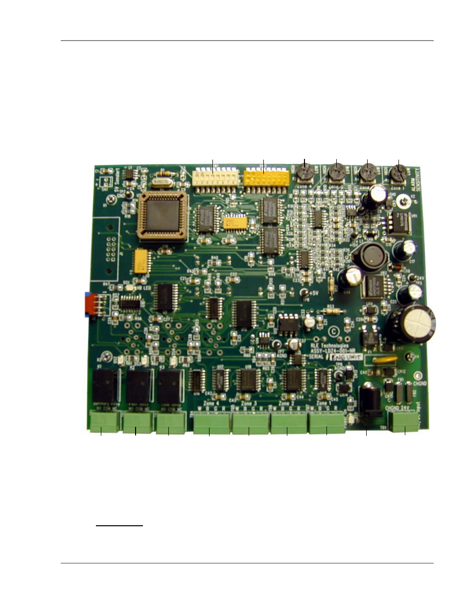
The LDZ4’s connectors, found at the bottom of the following photograph, are labeled TB4 through TB7.
The switches on the board are labeled SW1 and SW2. The unit has four dials that are used to adjust the
sensitivity for each zone. They are labeled R2 trough R5.
Figure 2-1: LDZ4 Leak Detection Board
2-1.1 TB8 – Power
The LDZ4 connects to a 24VAC/24VDC power supply using TB8, a three position connector labeled 24V.
TB7 –
Zone 1
Input
TB1 –
Summary
Relay
TB4 –
Zone 4
Input
TB3 –
Leak
Relay
TB2 –
Fault
Relay
TB5 –
Zone 3
Input
TB6 –
Zone 2
Input
P1 –
Power
Input
TB8 –
Power
Input
SW1– Relays
and Alarm
R4 –
Zone 1
Sensitivity Adjustments
R2 –
Zone 4
R3 –
Zone 3
SW2 –
Not Used
R4 –
Zone 2