Installation, Before you begin, Connecting the water leak detection cable – RLE LDZ4 User Manual
Page 12: Secure the cable to the floor, Chapter 3: installation, Figure 3-1: water leak detection cable
Chapter 3: Installation
User Guide: LDZ4
6 970.484.6510
www.rletech.com
CHAPTER 3: INSTALLATION
3-1
BEFORE YOU BEGIN
The LDZ4 is a wall mounted device. To secure the device to the wall, first open the door of the enclosure.
There are knockouts on the top and bottom of the enclosure. Remove as many as necessary. Use drywall
anchors and the holes in the back of the enclosure to secure the unit to the wall. Remember to close the
door and secure the latch when installation is complete.
3-2
CONNECTING THE WATER LEAK DETECTION CABLE
The LDZ4 is packaged with four 15 foot lengths of leader cable. One end of this leader cable connects into
the LDZ4. This end of the cable is finished with a terminal connector. The other end features a mating
connector which connects with the water leak detection cable. The end of the cable zone is finished with a
removable end terminator.
To connect the leader cable to the LDZ4, connect the wires (4) to the 4 position terminal connector, then
plug the terminal connector into the appropriate terminal block. From left to right, with the screws of the
connector facing up, the wires that screw into the terminal connector should be colored white, black, green,
and red. If the terminal connector is removed from the end of the cable, make sure the wires are in this
same order when the connector is reapplied. Terminal block and zone correlation information is found in
section 1.2 of this user guide.
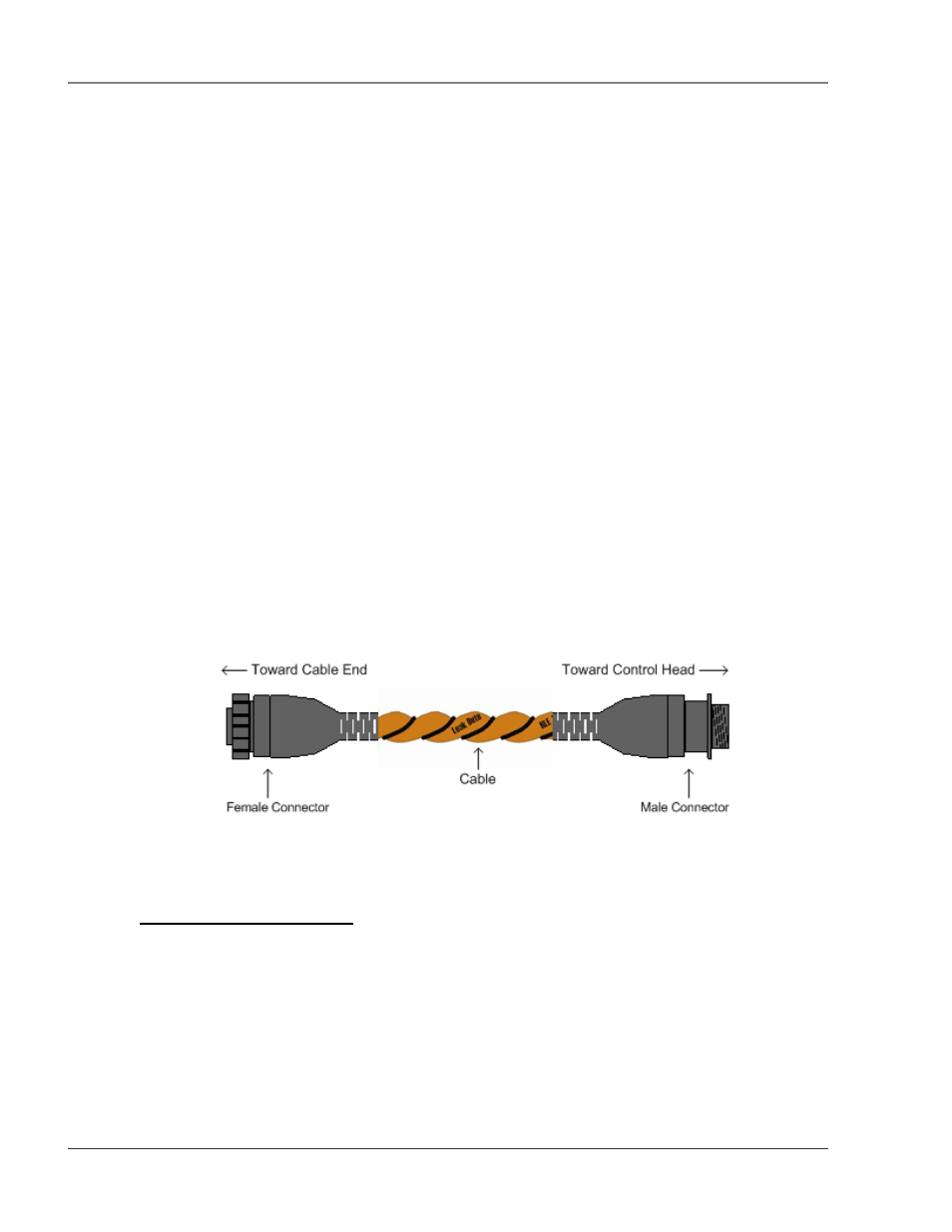
Once the leader cable is plugged into the terminal blocks, it is ready to be connected to the water leak
detection cable. To do this, unscrew the end terminator from the end of the leader cable. Attach the first
length of sensing cable to the leader cable. Route the sensing cable according to the cable layout diagram,
if provided. Lay the cable according to the following guidelines. Secure the end terminator on the
unoccupied end of the water leak detection cable.
Figure 3-1: Water Leak Detection Cable
3-2.1 Secure the Cable to the Floor
Secure the cable to the floor with either J-clips or one of the other approved methods shown in Figure 3-2.
J-clips are the manufacturer’s recommended installation method.
• Place one J-clip every three feet along the length of the sensing cable. Place one J-clip at each
turn of the cable.
• If the cable is installed over an obstruction, clip the cable on both sides, as close to the obstruction
as possible.
• Do not install the cable directly in front of an air conditioner. Allow a minimum of six feet
between the unit and the cable. If the cable is too close to the air conditioning unit’s air stream, the