Msp 217 tx sdi to fiber panel, 1:power interface, Indicator – RGBLink MSP 217 User Manual User Manual
Page 22: Sdi input interface, 5:usb interface, Hardware orientation
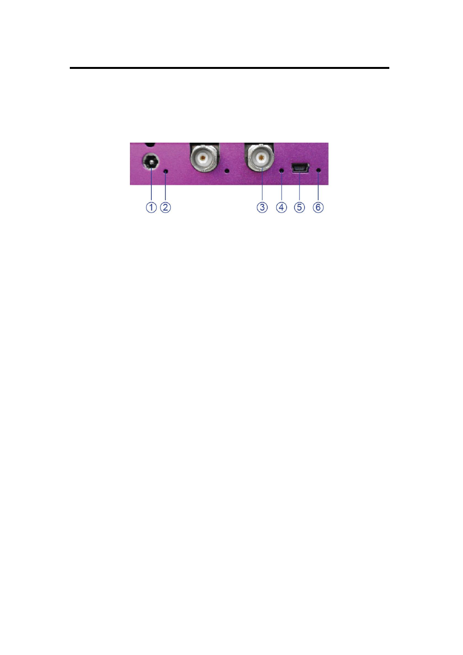
2. Hardware Orientation
MSP 217 TX SDI to Fiber Panel
MSP 217 User Manual 22
The figure below illustrates the professional interface and control signals
of MSP 217 SDI to Fiber panel:
1:Power interface
The device uses the standard 12V/1.5A power supply.
2.4.6: Indicator
Power indicator 2 lights when device has power supply.
LED indicator 4 is on when connect SDI cable and the device is in normal
Operation.
LED indicator 6 is on when connect USB cable and the device is in normal
Operation.
3: SDI input interface
SDI input interface,Can receive video signal from HD player, and HD
camera, connect interface 16 via 75 ohms impedance BNC port. Connect
LED screens via network cable.
5:USB Interface
Remote communication device control interface, used to connect to the
computer or console.
- Driver 2A Quick Start (2 pages)
- VSP 112U (15 pages)
- VSP 112U (108 pages)
- VENUS X1 Quick Start (19 pages)
- Driver User Manual (44 pages)
- New Driver Quick Start (22 pages)
- New Driver 2 User Manual (50 pages)
- MVP 320 Quick Start (2 pages)
- New Driver 2 Quick Start (27 pages)
- MSP 215A (6 pages)
- MSP 204 Quick Start (2 pages)
- MVP 320 User Manual (60 pages)
- VENUS X1 User Manual (135 pages)
- MSP 203 User Manual (37 pages)
- VENUS X3 Quick Start (37 pages)
- VSP 628PRO Quick Start (32 pages)
- VSP 168HD Quick Start (19 pages)
- VSP 168HD User Manual (100 pages)
- VSP 628PRO User Manual (120 pages)
- VENUS X2 Quick Start (31 pages)
- VSP 3550S Quick Start (4 pages)
- VSP 5162PRO (114 pages)
- VSP 5162PRO (18 pages)
- DV4 Quick Start (2 pages)
- VENUS X2 User Manual (68 pages)
- DV4 User Manual (31 pages)
- Driver Quick Start (17 pages)
- VSP 3550S User Manual (88 pages)
- Driver 4 Quick Start (2 pages)
- TSH4 Quick Start (1 page)
- VSP 5360 (110 pages)
- VSP 5360 (16 pages)
- TSH4 User Manual (31 pages)
- CP 3096 Quick Start (18 pages)
- CP 2048 (5 pages)
- DXP A1616 Quick Start (3 pages)
- CP 3072 Quick Start (18 pages)
- DXP D1616 Quick Start (13 pages)
- DXP D0404 Quick Start (1 page)
- DXP A1616 User Manual (50 pages)
- DXP D0108 Quick Start (1 page)
- CP 3072 User Manual (75 pages)
- DXP D0404 User Manual (30 pages)
- DXP D0108 User Manual (31 pages)
- DXP D1616 User Manual (76 pages)