Step 2: program source – RGBLink CP 2048 User Manual
Page 4
CP 2048 Control VSP 5360
Step 1: Connect to CP 2048
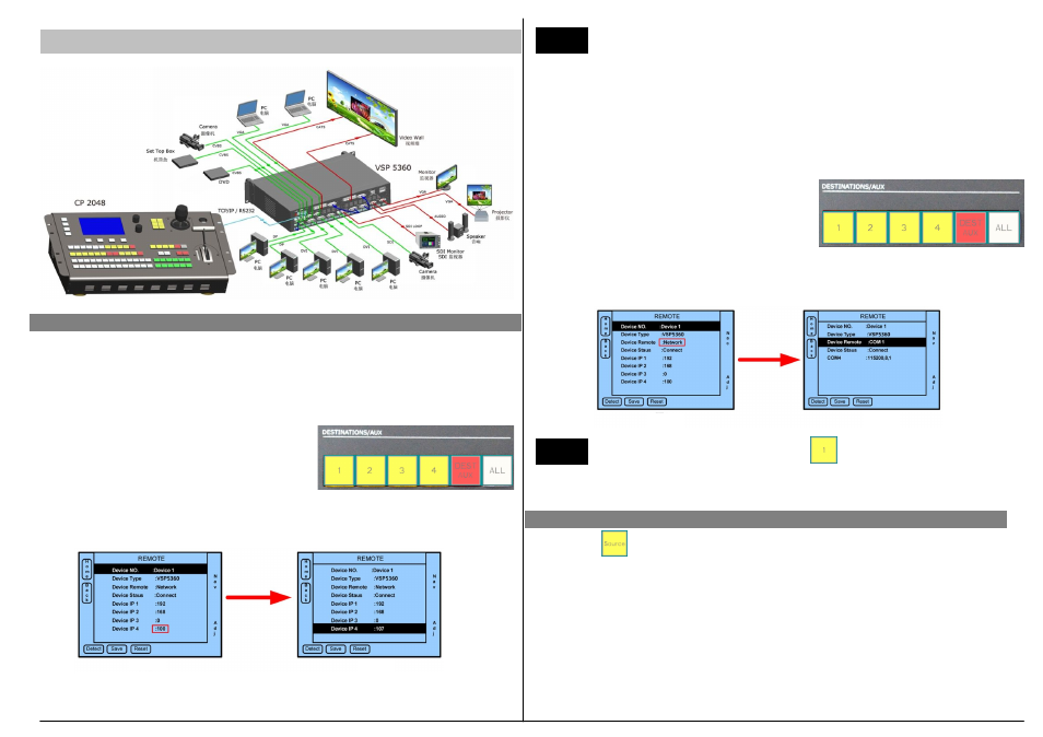
1. Control CP 2048 via network.
1) Set IP address for VSP 5360.
Connect VSP 5360 and CP 2048 by connecting CAT5 cable to LAN network port.
Operate on the VSP 5360 front panel and set the VSP 5360 IP, by
MENU-->SYSTEM--> ETHERNET-->IP-->192.168.0.
107
.
After the VSP 5360 IP address had been set, need to power off and on VSP 5360 again.
2) Set IP address for CP 2048.
①
Push anyone button on the "Destinations/AUX"
position (or via the options in REMOTE on the
Touch Screen Menu ) to select the corresponding
Device NO. 1~4, as shown in Picture 1 to select Device 1;
②
Set the CP 2048 IP address the same to VSP 5360 via change the option Device IP
4:
107
, as shown in Picture 2.
2. Control device via serial ports (using serial cables)
①
Push anyone button on the "Destinations/AUX"
position (or via the options in REMOTE on the
Touch Screen Menu) to select the corresponding
Device NO. 1~4, as shown in Picture 1 to select
Device 1.
②
Set the default Network in Device Remote to be COM by the knob. The actual
connection of VSP 5360 to CP 2048 is COM port, for example
COM 1
, as shown in
Picture 2.
After completing the above setup, push again to connect device. CP
2048 and VSP 5360 is auto-sync. If there is a Device Unconnected note on the LCD
screen of CP 2048, please check the above steps again .
NOTE
Step 2: Program Source
NOTE
Device No.: Series number of Device 1~4.
Device Type: Type of being controlled devices, including VSP 3600, VSP 729, DXP
1616, DXP 0808, MVP 8043, VSP 5350V+U, VSP 5350D+D, VSP 5350S+D, VSP
5350U+D, VSP 5350+D, VSP 5350V, VSP 5350D, VSP 5350S, VSP 5350U, VSP 5350,
VSP 5360V+D, VSP 5360D+D, VSP 5360S+D, VSP 5360U+D, VSP 5360+D, VSP
5360V, VSP 5360D, VSP 5360S, VSP 5360U and VSP 5360.
Device Remote: The network and serial ports for control.
Device Status: The state of control.
Push button or via INPUT options on the touch screen ( as picture 1) to active the
input source program menu ( as picture 2). User can program inputs to each of the 5
layers by the knob or touch screen.
Push button 1~13 in Preview area to select the source. For example, DVI1 to layer 1,
VGA2 to layer 2, DVI1 to layer 3 and CV2 to layer 4 ( as picture 3).
Picture 1
Picture 2
Picture 1
Picture 2