Remko cmf / cmt – REMKO CMF-80 v.2 User Manual
Page 28
REMKO CMF / CMT
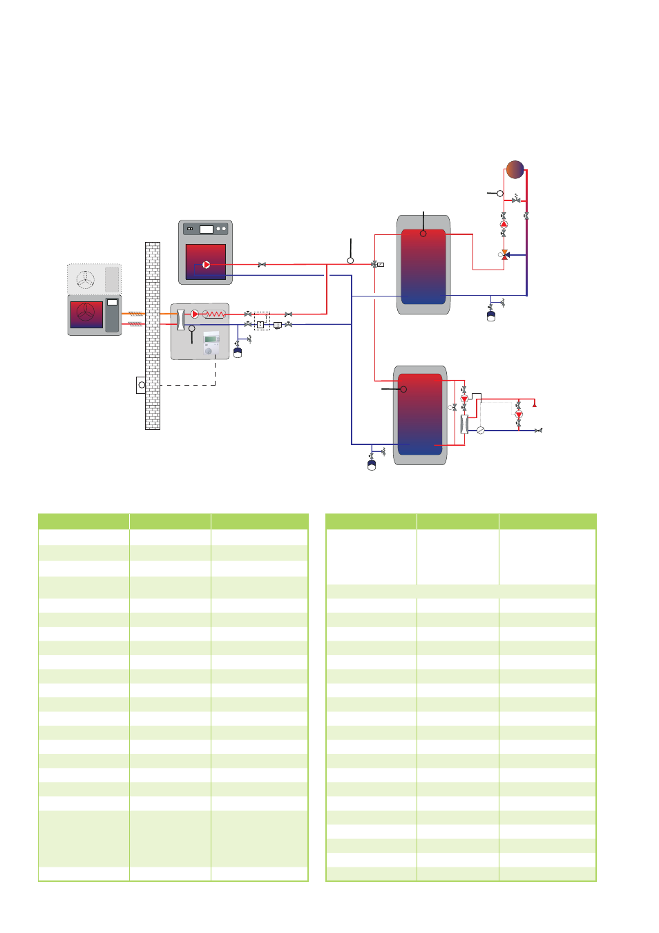
System example 4: Heat pump CMF 80, CMF 140 in bivalent mode with solid fuel boiler
Designation
Range of values
System example 4
Language
D/GB/F/NL/E/I
D - German
Time
0 - 24 hours
Set time
Date
Year, month, day
Set date
BUS code BM
Off, 01-15
Off
Terminal address
Off, 01 - 30
01
Regulator address
01 - 16
01
Bus code 1
00 - 15
01
Bus code 2
00 - 15
02
System selection
----, 01 - 13
12
Regulator type
00 – 06
06
WE1 Type
00 – 07
07
WE1 BUS
00 – 05
20
Gradient
On / Off
Off
WE2 Type
00 – 22
01
WE2 storage
00 - 03
00
WE3 Type
00 – 09
01
WE4 Type
00 – 09
00
Buffer type
00, 01, 02
00
Cooling mode
Off/ On
Off
HK1 function
Standard,T-feed
const, swimming
pool, WW,
return
Standard
HK2 function
See HK1
Standard
Designation
Range of values
System example 4
Output/level
00 – 9950 kW
WE 1 level 1 = 50
WE 2 level 1 = 1
WE 3 level 1 = 1
Continue with key next to "end"
MF1 function
00 - 34
00
T-MF1 setpoint
10° – 90°
---
MF1 Hyst
2K – 10K
---
MF1 Hyst off
2K – 10K
---
MF2 function
00 - 34
05
T-MF2 setpoint
10° – 90°
---
MF2 Hyst
2K – 10K
---
MF2 Hyst off
2K – 10K
---
MF3 function
00 - 34
10
T-MF3 setpoint
10° – 90°
---
MF3 Hyst
2K – 10K
---
MF3 Hyst off
2K – 10K
---
MF4 function
00 - 34
22
T-MF4 setpoint
10° – 90°
---
MF4 Hyst
2K – 10K
---
MF4 Hyst off
2K – 10K
---
F15 function
00 - 08
07
E1 function
00 - 03
02
E2 function
00 - 03
00
5K sensors
5K, 1K
5 K
M
Heating circuit
M
M
Buffer tank
Solid fuel
boiler
Storage
system (tank)
TS
Chilled water
Flow
control
Circulation
pump
Filling station
Indoor unit CMF
1)
0000
2)
3) The circulation pump have to be controlled separately
3)
Outdoor unit
The quantity of necessary sensors have to be controlled!
1) Proposed position for the heat meter (2,5m³/h)
2) Proposal: Use of energy efficiency pumps
F 8
F 6
F 17
F 9
AB
A
B
F 11
F 5
intake
28