Installation of the outdoor module – REMKO CMF-80 v.2 User Manual
Page 13
Pre-cut recesses
■
The device may only be at-
tached to a load-bearing con-
struction or wall.
■
Install the device on fl oor con-
soles with vibration dampers to
minimise noise.
■
The specifi ed minimum clear-
ances should be maintained
when carrying out the instal-
lation. These protective zones
serve to ensure unrestricted
air inlet and outlet. It must be
ensured that there is suffi cient
space available for installation,
maintenance and repairs.
■
The site of installation should
be well ventilated.
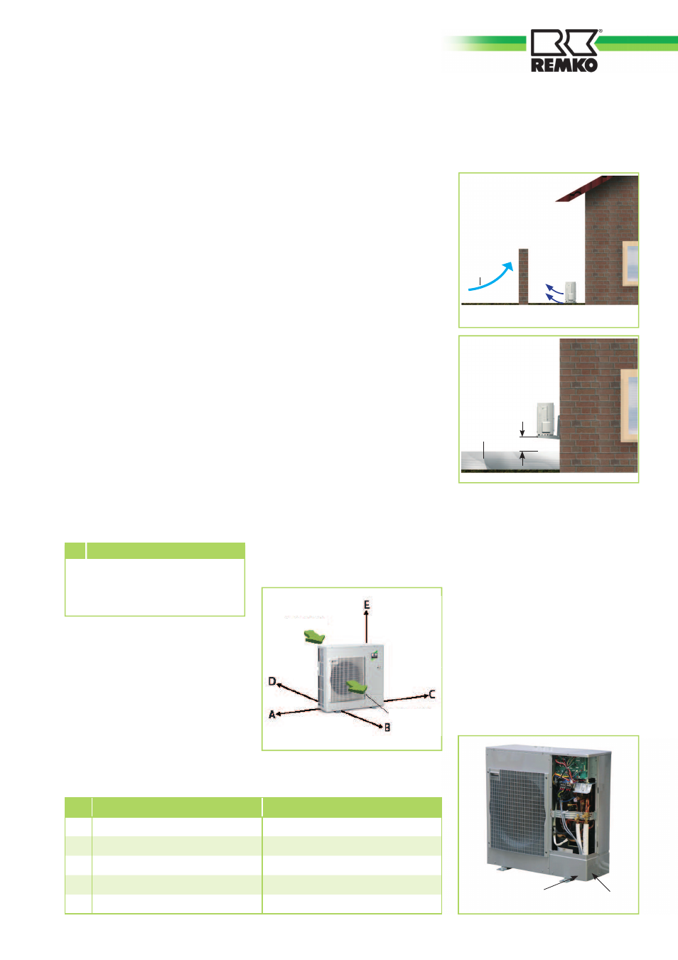
Installation of the outdoor module
Wind
20 cm
Snow
CMF 80 / CMF 90 / CMT 100
CMF 140 / CMF 150 / CMT 150
A
min. 50 mm
min. 50 mm
B
min. 750 mm
min. 1,000 mm
C
min. 150 mm
min. 150 mm
D
min. 250 mm
min. 500 mm
E
min. 100 mm
min. 100 mm
■
If the outdoor module is
erected in an area where there
is strong wind, then the device
must be protected from the
wind. The snow line is to be ob-
served during installation (see
fi gures).
■
It is to be ensured that the
outdoor module is only installed
vertically.
■
The outdoor module is at-
tached by means of 4 screws
with vibration dampers on fl oor
consoles.
Vibration dampers must also
be used when installing the
equipment with a wall bracket.
The vibration dampers serve to
reduce the noise transmittance.
■
The Water Ecology Act is to be
observed.
A number of sides must have
greater clearance that the mini-
mum specified clearance.
CAUTION
■
A heatable condensate catch
pan ensures that condensation
from the pan is able to drain
off.It must be ensured that the
condensation water is frost-pro-
tected in order that it can drain
off (gravel, drainage).
The right-hand side wall of the
device is to be removed before
installing the electrical cables and
the refrigerant line to the outdoor
module. In order to do so, release
the three screws on the side wall
and pull the panel downwards. If
there is insuffi cient room under-
neath the device for the refrigerant
lines, then the precut recesses can
be removed from the lower enclo-
sure panel and the pipes can be
guided in through these openings.
Air intake
Air outlet
13