Wiring diagram 400v fan motor – REMKO VRS Series User Manual
Page 25
25
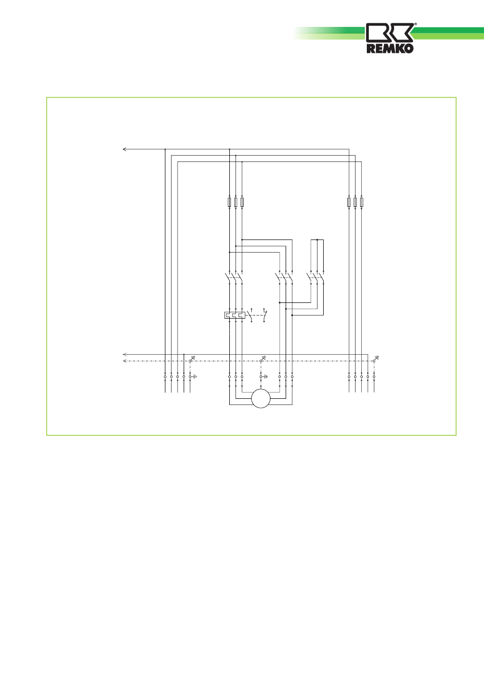
Wiring diagram 400V fan motor
L1
PE
L1 L2 L3 N
L1 L2 L3 N PE
U1
V1
W1
W2
U2
V2
N
PE
X1
M1
F3
K1
K2
K3
F1
F2
1 2 3 4
5 6 7
8 9 10
11 12 13 14
2 4 6
1 3 5
2 4 6
1 3 5
2 4 6
1 3 5
2 4 6
1 3 5
2 4 6
1 3 5
2 4 6
1 3 5
97
96
98
95
Ventilatormotor
400V/3~ N
für optionalen
3~ Brennermotor
M
3~
Legende:
F1 = Fuse block, fan motor
F2 = Fuse block, burner motor (optional)
F3 = Thermal overcurrent relay, fan motor
F4 = Control fuse
H1 = Fan fault indicator light
H2 = Fan operating indicator light
H3 = Burner operating indicator light
H4 = Burner fault indicator light
KB = Triple function combination controller
K1 = Supply contactor
K2 = Delta contactor
K3 = Star contactor
K4 = Time limit relay
M1 = Fan motor
RT = Room thermostat or control (optional)
P = Time counter (optional)
S1 = Switch
STB = Safety temperature limiter
TR = Fan controller
TW = Temperature monitor
X1 = Terminal strip 1 in control box
X2 = Terminal strip 2 in control box
Fan motor:
400V/3~ (from 3.0 kW)
Burner motor: (400V/3~ optional)
We reserve the right to make dimensional and design changes in the interest of technical advances.