Remko vrs, Wiring diagram 230v – REMKO VRS Series User Manual
Page 22
22
REMKO VRS
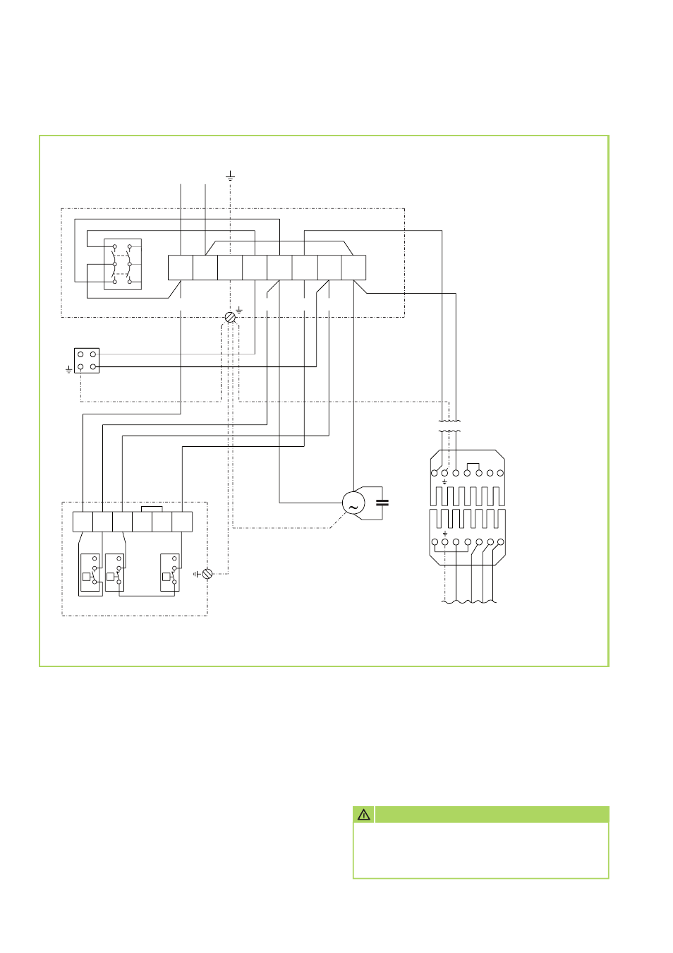
Wiring diagram 230V
2
3
1
5B
2A
#2
#3
#4
#1
sc
hw
ar
z
bl
au
bl
au
br
au
n
L1
N T1 T2 S3 B4
1
4
2
1
4
2
1
1
4
2
sc
hw
.1
sc
hw
.2
sc
hw
.4
sc
hw
.3
M
4B
1A
6B
3A
1
2
3
4
5
6
7
8
2
3
4
5
6
L1 N
S
KL
SK
WS
RT
TR TW
STB
KB
Wielandbuchse
vom Brenner
Wielandstecker
Nur im Lieferumfang
des werkseitigen
Brenners enthalten.
Brennerkabel
Werkseitig vorbereitet
zum Anschluß des
Wielandsteckers.
L1
N T1 T2 S3 B4
C
J
J
J
Legend:
C = Capacitor
KB = REMKO triple function combination controller
KL = Terminal strip in control box
M = Fan motor
RT = Thermostat socket
S = Switch
SK = Control box
STB = Safety temperature limiter
TR = Fan controller
TW = Temperature monitor
WS = Wieland connector
(only factory supplied burners)
An emergency switch must be provided at an
easily accessible point in the installation room
(however outside any danger zone) .
This switch must be protected against
unauthorised use!
Fan motor:
230V/1~
Burner motor: 230V/1~
We reserve the right to make dimensional and design changes in the interest of technical advances.
AttENtION
Electrical appliance connection must only be
carried out by authorised specialists in com-
pliance with DIN EN 60335-1/VDE 0116.