Safety device, Waste gas pipes – REMKO CLK 30 User Manual
Page 6
6
Information on the Safety Device
The device is equipped with a sensor monitoring feature
and is resistant to cool down to temperatures of -20°C;
below -20°C the device switches off; when the tempera-
ture rises above this temperature, it switches on again.
When the sensor or capillary tube is damaged, or when
an excess temperature of approximately 220°C is
reached, the liquid contained in the thermostat is emp-
tied and the device switches off for safety purposes.
The device is no longer operable and must be replaced
If it is necessary to replace the STB, only the original
REMKO part may be used.
à Make sure to install and mounting the device care-
fully.
à Do not bend the capillary tubes near to solder points.
à
When installing the capillary tubes, be careful not to
damage or bend them too sharply.
à The sensors may only be mounted in the mounting
brackets supplied by the manufacturer.
à The sensors must always be free from dust and dirt.
Safety Device
The device has 3 safety functions:
à Fan control (TR)
à Temperature monitor (TW)
à Safety temperature limiter (STB)
Fan control (TR)
The fan control switches the circulating air fan off and
on. The point at which the device is switched on or off is
set in the control box via the temperature control ther-
mostat “Scale 21 – 60”.
Rated value approx. 35 to 40°C.
Temperature Monitor (TW)
When the unit is in heating mode, the temperature
monitor limits both the temperature of the unit and the
air being blown out. The switching point is set via the
temperature control thermostat “Scale 34 – 110” in the
control box.
Rated value approx. 80 to 85°C.
Safety Temperature Limiter (STB)
The STB controls the temperature monitor. The switch-
ing point is fixed. The burner is prevented from being re-
started if the STB is activated.
After the cover next to the control panel is removed, the
reset button must be pressed from the outside.
After the STB has been reset, the cover must be replaced.
G
Before a STB reset, check the operating conditions
to ensure that the STB temperature is not ex-
ceeded again.
à The unit generally operates properly when the waste
gas pipes have been laid at an incline and assem-
bled with vertical end pipes.
à The waste gas pipes must reach at least beyond the
gutters but preferably above the top of the roof to
prevent counter pressure caused by weather condi-
tions (e.g. wind).
à All waste gas pipe components must be securely
fastened. They may not be smaller in diameter than
the waste gas connection.
à A minimum distance of 0.6 m must be maintained
from flammable objects.
à Waste gas components incl. fasteners can be pur-
chased as accessories.
Waste Gas Pipes
When the units are operated outside or in open rooms
you do not need a waste gas pipe. However, we recom-
mend using a waste gas pipe 1 m long (see example 2)
with a rain cover on top to prevent the penetration of
rainwater and dirt.
If the units are used as room heaters, it is necessary to
route the waste gases to the outside.
G
Make absolutely sure that counter pressure is not
created by improperly laid waste gas pipes.
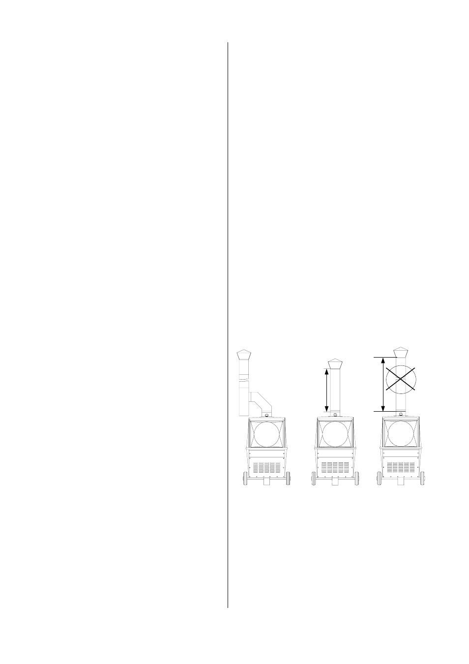
Important Information.
To prevent damage to the combustion chamber caused
by moisture build-up (condensation) (see example 3),
make sure that the waste gas pipes have a properly in-
stalled condensation trap (see example 1).
G
When using an waste gas connection, the burner
must be adjusted accordingly.
Example 1
Example 2
Example 3
Operation with
exhaust gas pipe
extended.
Requires conden-
sation trap
Operation without
exhaust gas pipe
extended.
max. 1 meter
Inadmissible
installation.
ma
x
.
1 m
.
m
ore t
han 1 m
.