Wiring diagram, Tw rt tr stb s1 ws – REMKO CLK 30 User Manual
Page 13
13
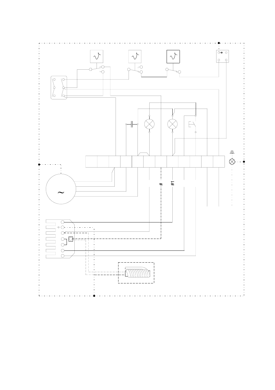
Wiring Diagram
TW
RT
TR
STB
S1
WS
1A
2A
3A
4B
5B
6B
H2
H1
KL
1
2
3
4
5
6
7
8
9
L1
N
T1
T2
S3
B4
I
0
II
C
10
2
1
3
S2
M
N
braun
orange
schwarz
1
1
1
2
2
2
4
4
#2
#4
#3
HW 04.03
N
PE
L1
N
ÖV
5
blau
oil preheater
Optional: with CLK 30 / 50 / 70.
Standard: with CLK 120 / 150 (
only if burner
has been installed at our factory
)
brown
orange
black
blue
C = capacitor
S2 = external reset button (burner)
H1 = control lamp, green
STB = safety temperature limiter
H2 = control lamp, red
TR = fan control thermostat
KL = terminal strip
TW = temperature monitor thermostat
M = fan motor
WS = plug to burner, 7-pole
(only if burner has been installed at our factory)
RT = room thermostat socket
ÖV = oil preheater
S1 = operating switch