7 electrical connection, Electrical connection – REMKO RKL 491 DC User Manual
Page 17
7
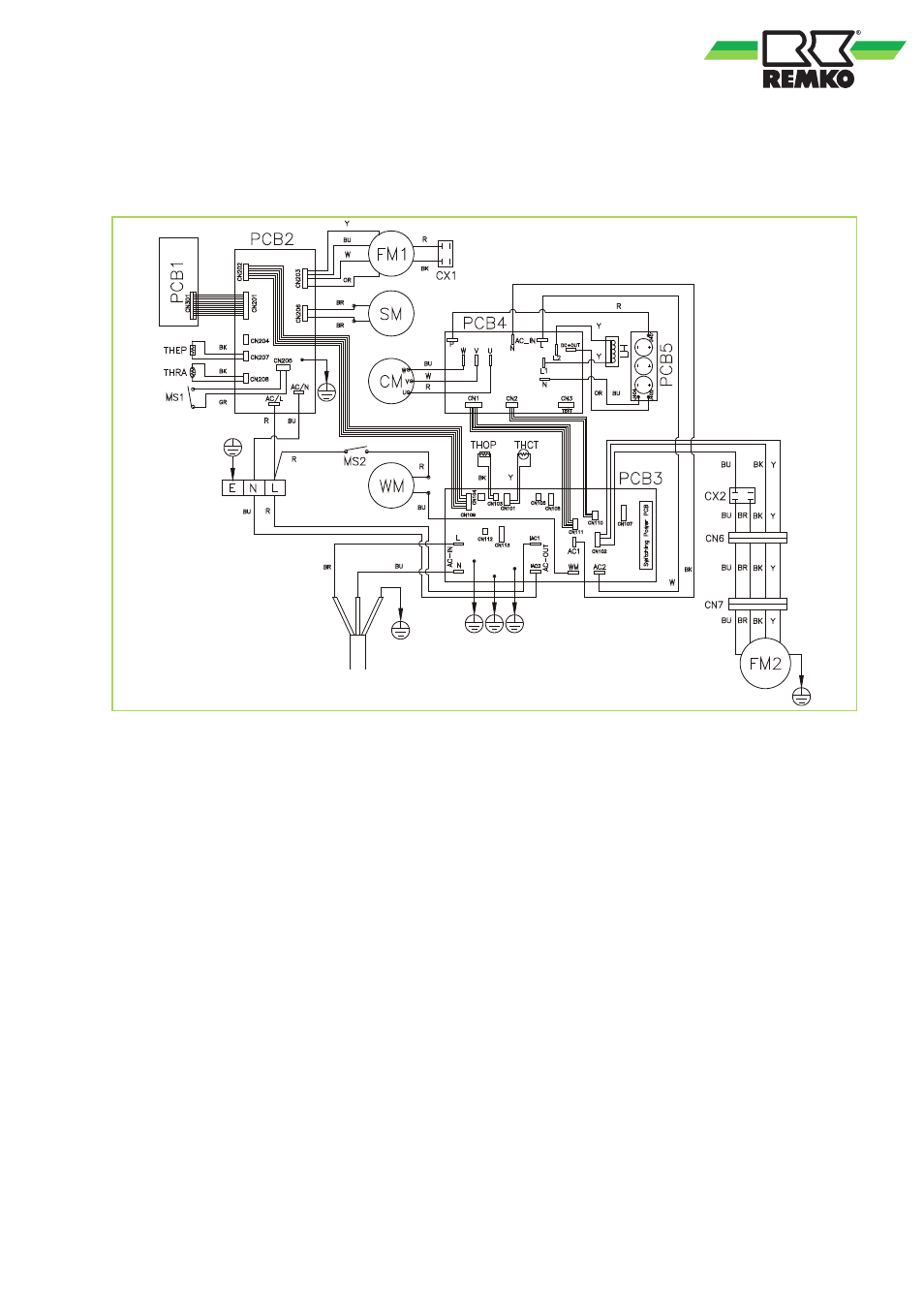
Electrical connection
Electrical connection diagram
Fig. 17: Electrical connection diagram
PCB1
Control board
PCB2
Main board
SM
Swing motor
FM1
Vaporiser fan
FM2
Condenser fan
WM
Condensate pump
CM
Compressor
OLP
Compressor excessive temperature protec-
tion
CX1
Condenser, vaporiser fan
CX2
Condenser, condenser fan
CX3
Condenser compressor
RT
Sensor circulating air temperature
CT
Sensor frost protection
MS1
Microswitch alarm (container full)
MS2
Microswitch condensate pump
Colour code:
BK
Black
BR
Brown
BU
Blue
GR
Gray
OR
Orange
R
Red
W
White
Y
Yellow
17
This manual is related to the following products:
See also other documents in the category REMKO Conditioners:
- RKL 360 S-LINE (28 pages)
- MKT 291 S-LINE (28 pages)
- BL 352 DC (56 pages)
- ML 523 DC (64 pages)
- MXD 522 (48 pages)
- MXW 522 (44 pages)
- PWL 303 HK (24 pages)
- RVT 683 DC (72 pages)
- WLT 85 (24 pages)
- RVS 150 H (44 pages)
- KWL Series (48 pages)
- MKT 240 (12 pages)
- MKT 250 (12 pages)
- MKT 260 (16 pages)
- RKL 350 (16 pages)
- MKT 290 (20 pages)
- RKL 480 (16 pages)
- RKL 240 (16 pages)
- RKL 490 DC (20 pages)
- ATY 351 (28 pages)
- ATY 350 (32 pages)
- ATY 351 DC (36 pages)
- MD 351 (32 pages)
- ML 280 (24 pages)
- BL 351 (32 pages)
- ML 522 DC (32 pages)
- MVT 1050 DC (28 pages)
- MXD 520 v.3 (28 pages)
- MXD 520 v.1 (28 pages)
- RKS 448 H (20 pages)
- RKS 524 H (16 pages)
- RKS 371 H (28 pages)
- RKV 24 W (20 pages)
- RKV 24 T (20 pages)
- RKV 24 C (24 pages)
- RKW INOX (28 pages)
- RVD 521 DC (32 pages)
- RM Series (36 pages)
- RVD xxx DC (52 pages)
- RWH 680 (20 pages)
- RVT 521 DC (32 pages)
- RXS xxx H (20 pages)
- RXD Series (28 pages)
- RXW 480 (20 pages)