Ravenheat CSI 85 User Manual
Page 45
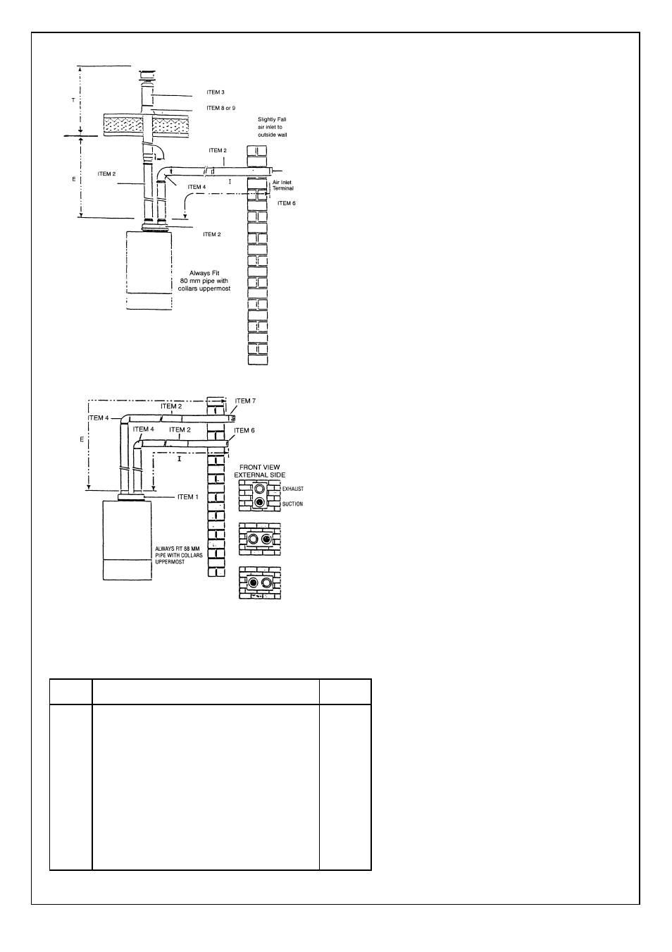
Fig. 65
Fig. 66
45
ITEM
DESCRIPTION
PART NO
1
2
3
4
5
6
7
8
9
10
CSI fl ue adaptor gasket and screws
Straight pipe
Eccentric vertical terminal
90º slow bend
45º bend
Air inlet terminal (plastic) 80 mm
Exhaust terminal (stainless steel) 80 mm
Pitch roof slate
Flat roof slate
Twin fl ue pipe socket seal 60 mm
30005
30001
30003
30009
30011
30007
Exhaust/suction system with two separate rated 80 dia.
Pipes - exhaust on fl at or sloping roof, suction from vertical
wall.
Maximum distance D = I + E + T = Total exhaust/inlet pipe
= 20 metre.
Exhaust terminal must not be cut.
Min inlet pipe distance = 0.5 metre.
NOTE: The pressure loss for each elbow is:
90° slow bend less 3 metre of pipe for each one fi tted
45° bend less 1.5 metre of pipe for each one fi tted
Minimum total length = 2 metre
NOTE: Exhaust fl ue must slope 2° down towards the boiler
35 mm fall per metre.
IMPORTANT:
see Fig. 6 and 29 for terminal clearances.
Exhaust/suction system with two separate pipes through a
single vertical wall.
Maximum distance D = I + E = Total exhaust/inlet pipe 18
metre.
Minimum distance D = I + E = 1.5 metre.
Min inlet pipe distance 0.5 metre.
Min distance between pipe 50 mm.
NOTE. The pressure loss for each elbow fi tted is:
90° slow bend less 3 metre of pipe for each one fi tted.
45° bend less 1.5 metre of pipe for each one fi tted.
IMPORTANT: inlet and exhaust terminals must
never be installed on opposite walls of the building
(PrEN 483).
IMPORTANT NOTICE: If the fl ue terminates less
than 2 m. above a balcony, above the ground, or
above a fl at roof to which people have access,
then a suitable terminal guard must be fi tted.
Fit only recommended fl ue terminal guard by
securing concetrically around terminal with
screws.
Available on request from:
RAVENHEAT MANUFACTURING LTD
Chartist Way
Morley, Leeds, West Yorkshire
ENGLAND LS27 9ET - U.K.
Tel. (0113) 252 7007
IMPORTANT:
see Fig. 6 and 29 for terminal clearances.