Ravenheat CSI 85 User Manual
Page 24
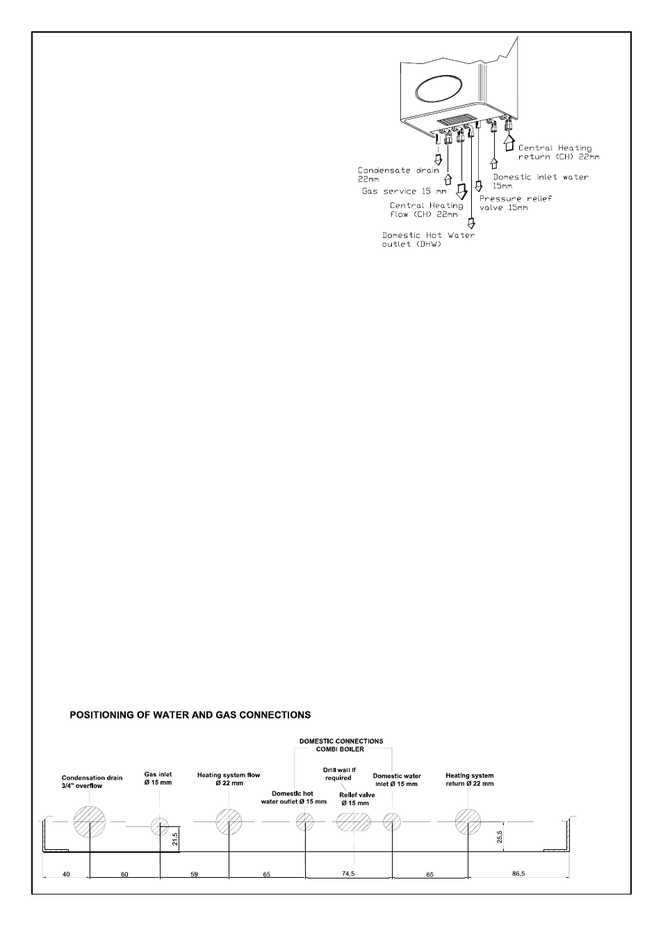
Fig. 32
24
5.12 SAFETY VALVE DISCHARGE AND
CONDENSATE DRAIN CONNECTION.
5.12.1
The safety valve is located on the flow manifold,
and discharge pipe is located between DHW
cold inlet and DHW hot outlet.
The discharge should terminate facing
downward exterior to the building in a
position where discharging (possibly boiling
water & steam) will not create danger or
nuisance, in a easily visible position, not to
cause damage to electrical components or
wiring.
The discharge must not be over an entrance
or a window or any other type of access.
5.13 ELECTRICAL
CONNECTIONS
5.13.1 IMPORTANT: Electricity supply must be as
specified in clause (sect. 4.10).
- When controls external to the appliance
are required, design of the external
electrical circuits should be undertaken by
a competent person. In accordance with the
IEE wiring regulations.
It is essential that all external controls
must be volt free.
Factory fitted internal wiring must not be
disturbed when wiring external controls.
- To gain access to the electrical box remove
the front panel of the case as described in
clauses (sect. 5.4).
- The terminals are easily visible on the side
of the control electronic box.
-
Heat resistant flexible cable is fitted
between the isolator and the terminal block
A 3 core cable of 0.75 mm
2
(24x0,2 mm) to
BS 6500.
Make sure all wires to the appliance are
routed away from sharp edges and hot
surfaces.
The cable must be fastened with its cord
anchorage and connected so that should the
cable slip from the anchorage the current
carrying conductors becomes taut before
the earthing conductor. Securely tighten all
terminal screws and arrange the cable with
slack between the cord anchorage and the
terminal block.
WARNING: If the supply cord is damaged,
it must be replaced by a service engineer
(supply cord available from Ravenheat
Manufacturing Ltd).
Fig. 33
5.12.2 The condensate drain connection is on the
left of Gas service cock (Fig.32).
A 25 mm plastic overflow pipe is fitted on
the condensing trap and should be used
to fit on the drain connection, if required,
to discharge condensate to a drain. The
drain pipe should have a fall of a least 2.5°
away from the boiler. Condensate should, if
possible be discharged into the household
internal drainage system.
If this is not practicable, discharge can be
allowed into the external household drains
or a purpose designed soak away.
It is recommended that any external
condensate drain pipe is insulated and also
preferably of 32 mm diameter, to prevent
freezing in adverse weather conditions.
The condensate is discharged periodically
in “ slugs” by siphonic action. It is not
necessary to provide air breaks or extra
traps in the discharge pipe as there is
already a 125mm high trap inside the boiler.
Fitting an extra trap may cause the boiler
siphon to work incorrectly.
Refer to BS5546 or BS6798 for advice on
disposal of boiler condensate.