Ravenheat CSI 85 User Manual
Page 34
34
7.14.3 Remove the switch out from the instrument
panel by pressing the clamp springs.
7.14.4 Replace in reverse order.
7.11
TO REMOVE/REPLACE THE INJECTORS
( fi g. 50).
7.11.1 Remove the front casing and the depression
chamber front cover (sect.7.3 - 7.4).
7.11.2
Unscrew the union and the 4 screws securing
the manifold at the burner.
7.11.3
Pull the manifold up and out from the
combustion chamber.
7.11.4 Unscrew and replace the injectors and their
seals.
7.11.5
Replace in reverse order.
7.11.6 Relocate the grommet, sealing the gas supply
pipe to the casing taking care not to damage
it. Replace if necessary.
7.12
TO REMOVE/REPLACE THE BURNER
7.12.1 Remove front casing (sect.7.3) and the
combustion chamber front cover (sect.7.4).
7.12.2 Remove the injectors manifold as described
in sect. 7.11.
7.12.3 Remove the two screws securing the main
burner to the combustion chamber (Fig 74).
7.12.4 Pull the burner forward and remove (fig. 49).
7.12.5 Replace in reverse order.
IMPORTANT:
When refitting the burner make
sure that the pins at the rear of the combustion
chamber locate into the slots made on the rear
of the burner.
7.13
TO REMOVE/REPLACE THE GAS VALVE
(fig.
36).
7.13.1 Remove front casing (sect.7.3) and the
combustion chamber front cover (sect.7.4).
7.13.2 Unscrew the union.
7.13.3 Remove the 2 screws to the gas pipeline.
7.13.4 Remove the eight screws (four per side) that
connect the gas valve to the gas pipelines and
then remove it from its seat.
7.13.5 Replace in reverse order, always using new seals.
7.14
TO REMOVE/REPLACE THE MAIN
SWITCH (fig. 35).
7.14.1 Remove front casing (sect. 7.3) and remove
the panel instrument.
7.14.2 Detach the wires that connect to the switch.
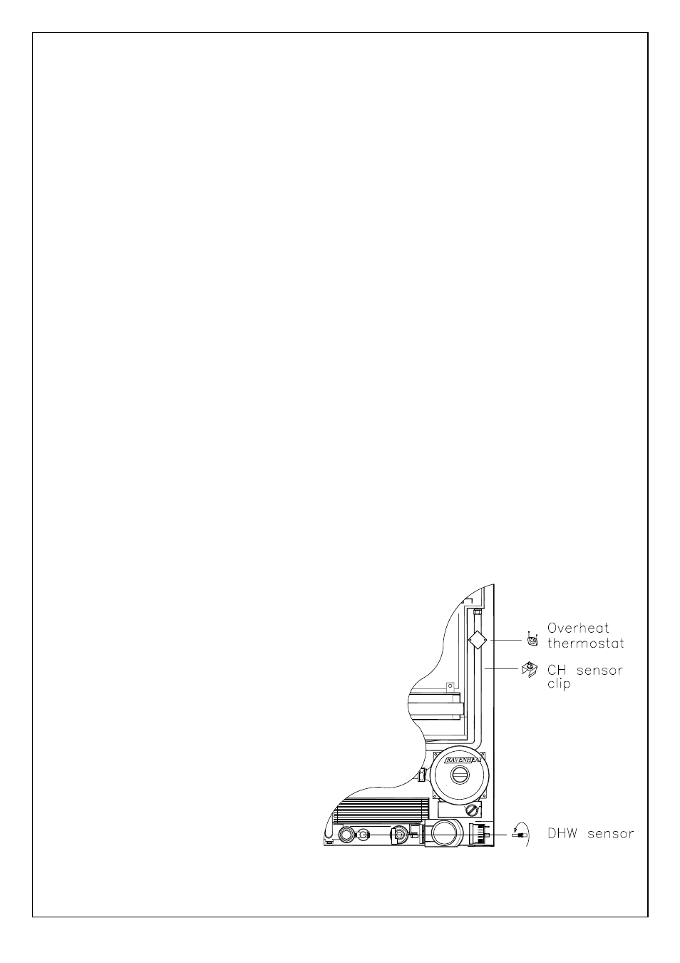
7.15 TO REMOVE/REPLACE THE HEATING AND/
OR HOT WATER CONTROL SENSOR.
7.15.1 Remove front casing (sect. 7.3).
7.15.2 Remove the wires that connect the sensors.
7.15.3 For C.H. thermistor remove the retaining clip
from the pipe.
Replace in reverse order.
7.15.4 For D.H.W. sensor close the on/off valves for
the domestic inlet water circuit and open
domestic hot water tap.
Unscrew the sensor and replace in reverse
order with new seal (fig. 46).
7.16
TO REMOVE/REPLACE THE OVERHEAT
THERMOSTAT.
7.16.1 Remove front casing (sect. 7.3).
7.16.2 Remove the two wires that connect to the
overheat
thermostat.
7.16.3 Remove the two screws securing the thermostat to
the pipe and pull it out.
7.16.4 Replace in reverse order (Fig.46).
Fig. 46