Side mount upgrade kit, Audio line out port – Posiflex FT-7715 User Manual
Page 9
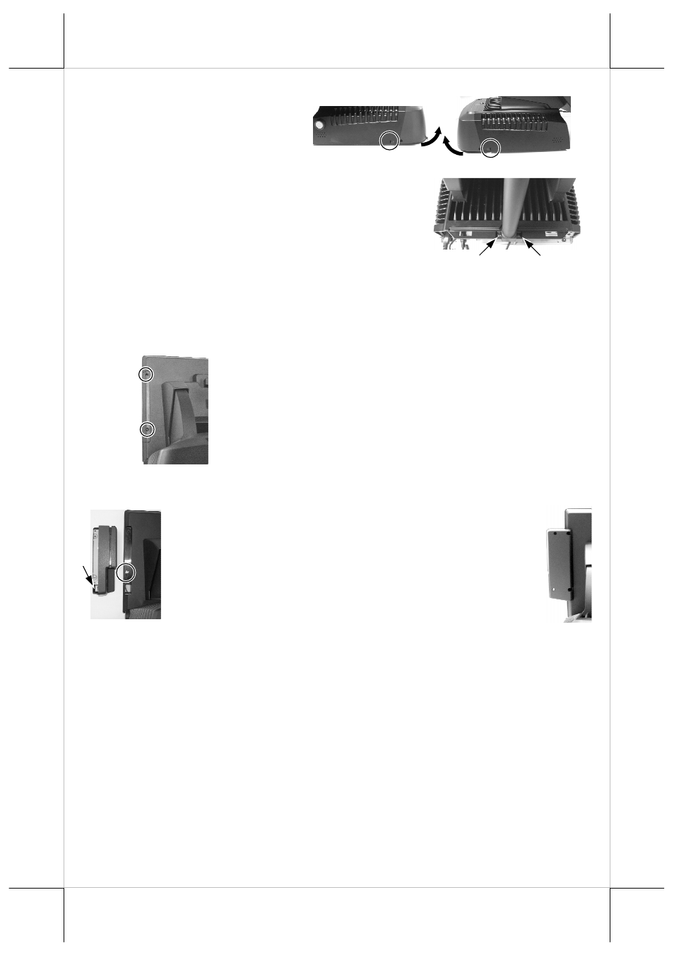
Part 9
to remove the back
cover.
2.
Remove the pole cover
on rear edge of the base top cover of FT
system by first removing the 2 arrowed
screws in the left picture and then pushing
the wedge shaped pole cover up.
3.
Insert the base of base mount upgrade kit
from top of FT system base with the flat
side of the pole base facing the back cover direction and screw back
the 2 screws as in the right picture. Connect the interface cable to
appropriate port.
SIDE MOUNT UPGRADE KIT
When a side-mount upgrade kit option such as FA-200 is
ordered with the FT-7715 system, this option is already installed in the
delivery. No matter the kit itself contains MSR only, finger print sensor only or
both options, the connection to the FT-7715 system is
through an internal cable in the right side cover of the
LCD/touch unit. Remove the 2 circled screws in the
left picture to remove the cover for side mount upgrade
kit. Take out the cable inside this cover as circled in
the left picture here and connect it to connector inside
the side mount upgrade kit as arrowed in the same
picture. Gently arrange the excessive length of this cable back in the hole and
screw-fit it back to the position originally occupied by the cover as in the right
picture. Please reserve the cover if there is chance to have the side mount kit
removed in the future.
AUDIO LINE OUT PORT
The audio output port is intended for BIOS POST sound and touch
buzzer sound, either one can be set individually. So this port must be
connected to a pair of speakers with built-in booster or amplifier only.