Parts identification – Posiflex FT-7715 User Manual
Page 4
Part 4
PARTS IDENTIFICATION
1.
Optional base mount kit
2.
Touch panel / LCD panel
3.
Optional side mount kit
4.
LOGO & Power indicator
5.
Base unit
6.
Front cover
7.
CFast memory card reader slot in front cover
8.
USB port in front cover
9.
LAN status indicator
10.
HDD1 status indicator
11.
LCD brightness / contrast adjust buttons
12.
LCD panel tilt adjust button
13.
Power switch button
14.
Acoustic vent
15.
Back cover release button
16.
Reserved back cover lockup screw hole
17.
Back cover
Please note that the picture for inside front and back cover is for reference
only. The actual layout may disagree from this picture if there is any
difference in model or options selected or in the system revision. Please
follow the actual layout for cable connections in this case.
CAUTION: DO NOT release the HDD compartment (items 36
and 37) or system damage may occur.
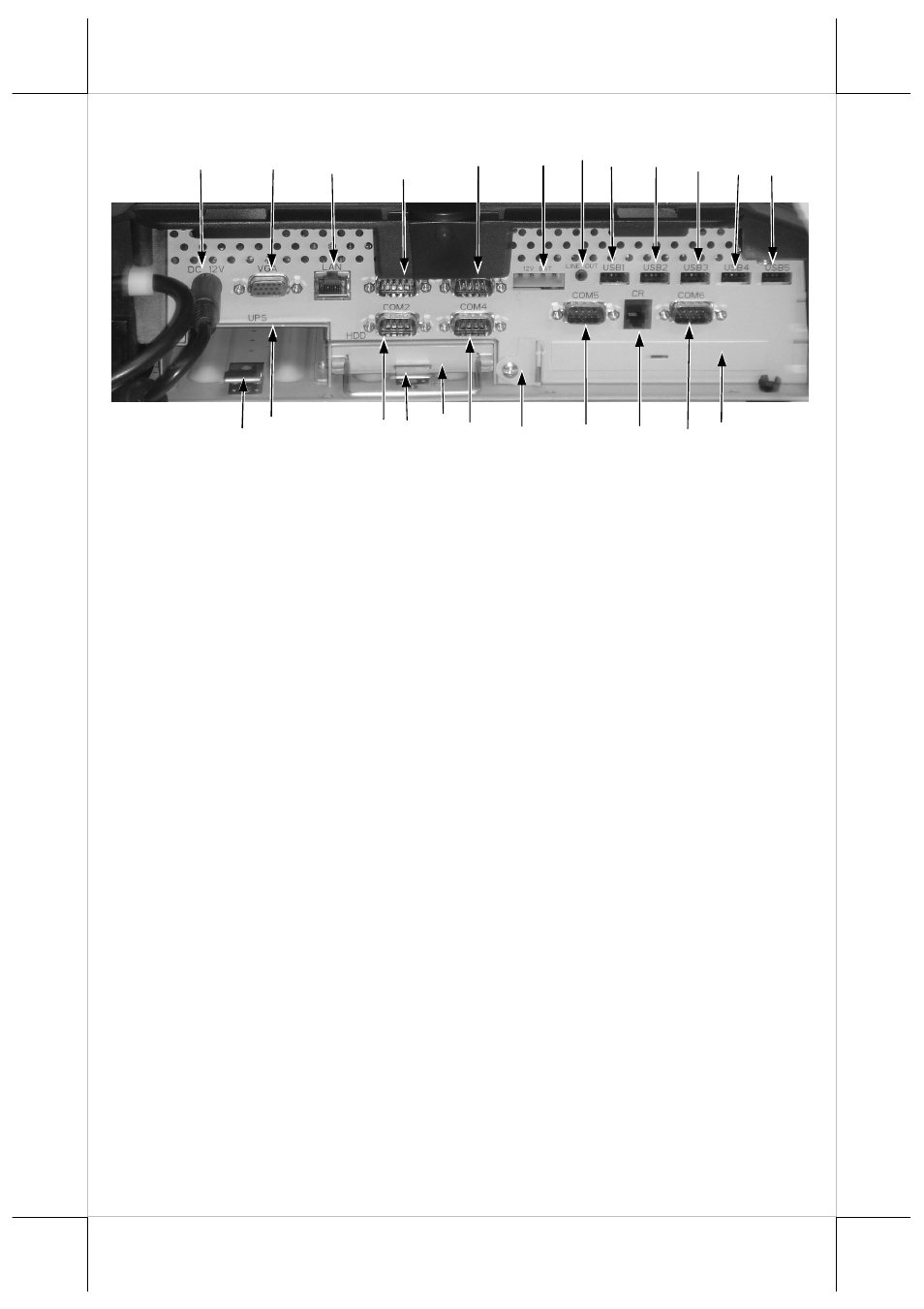
Detail inside back cover
23
29
25
20
19
32
22
31
21
26
18
38
36
33
39
24
34
30
37
28
27
35
40