Warning – Pennco 15B045FE User Manual
Page 30
30
APPENDIX A - CONTROL MODULE
STEP 3: Check spark ignition circuit.
Disconnect ignition cable at SPARK terminal on module.
WARNING
Electrical shock hazard. Ignition circuit generates
over 10,000 volts. Turn OFF electrical power
supply at service panel before making electrical
connections. Failure to do so could result in death
or serious injury.
!
Energize module and listen for audible sparking noise.
When operating normally, there should be buzzing noise
turns on and off twice per second for duration of 1–7
seconds, depending on model.
STEP 4: Verify pilot and main burner lightoff.
• Initiate call for heat. Turn thermostat above room
temperature. Ignition sequence may be delayed by
thermal purge until boiler water temperature is below
140°F (60°C)
• Watch pilot burner during ignition sequence.
— Verify ignition spark continues after pilot is lit.
— Verify pilot lights and spark stops, verify main
burner does not light.
• If so, ensure adequate flame current as follows.
— Turn off boiler at circuit breaker or fuse box.
— Clean flame rod with emery cloth.
— Verify electrical connections are clean and tight.
Replace damaged wire..
— Check for cracked ceramic insulator, which can
cause short to ground, and replace igniter-sensor if
necessary.
— At gas valve, disconnect main valve wire from MV
terminal.
— Turn on power and set thermostat to call for heat. Pilot
should light, main burner will remain off because main
valve actuator is disconnected.
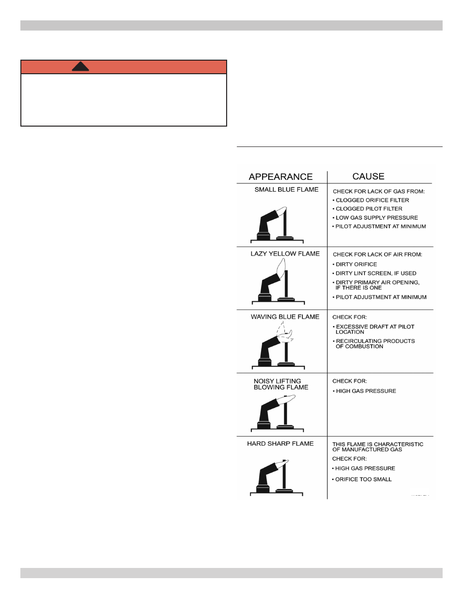
— Check pilot flame. Verify it is blue, steady and
envelops 3/8 to 1/2 in. [10 to 13 mm] of flame rod.
Figure 22 for possible flame problems and causes.
— If necessary, adjust pilot flame by turning pilot
adjustment screw on gas control clockwise to decrease
or counterclockwise to increase pilot flame. Following
adjustment, always replace pilot adjustment cover
screw and tighten firmly to assure proper gas control
operation. Figure 14, Page 20.
— Set temperature below room set-point to end call for
heat.
• Recheck ignition sequence as follows.
— Reconnect main valve wire.
— Adjust thermostat above room temperature.
— Verify ignition sequence at burner.
— If spark does not stop after pilot lights, replace
module.
— If main burner does not light or if main burner lights
and system locks out, check module, ground wire and
gas control as described in troubleshooting table. See
Table 9, Page 35.
Figure 22
- Pilot Flame
Correct Pilot Flame: 3/8 to 1/2 inch in
flame. See Figure 18, Page 22.