Pennco 15B045FE User Manual
Page 25
25
Gas input to boiler can be adjusted by removing protective
cap on pressure regulator Figure 14, Page 20 and
turning screw clockwise
to increase input and
counterclockwise
to decrease input. Manifold
pressures are taken at outlet side of gas valve. See
Figure 14, Page 20. To check for proper flow of natural
gas to boiler, divide input rate shown on rating plate by
heating value of gas obtained from local gas company. This
will determine number of cubic feet of gas required per
hour. With all other gas appliances off, determine flow of
gas through meter for two minutes and multiply by 30 to
get hourly rate. Make minor adjustments to gas input as
described above.
Burner orifices should be changed if final manifold pressure
varies more than plus or minus 0.3 inches water column
from specified pressure.
Primary air adjustment is not necessary, therefore air
shutters are not furnished as standard equipment. Air
shutters can be furnished on request where required by
local codes or conditions.
CHECK SAFETY CONTROL CIRCUIT. Ignition system
safety shutoff device must be tested after placing boiler in
operation.
Intermittent Pilot: With main burner operating, turn
pilot gas adjusting screw clockwise
until pilot gas is
turned off. See Figure 14, Page 20 Within 90 seconds main
gas control should close, shutting off gas to main burner.
High Limit Control (Figure 23): Remove cover and note
temperature setting. Decrease this setting to minimum
and operate boiler. When boiler water temperature exceeds
control temperature setting, control will open circuit,
closing automatic main gas valve.
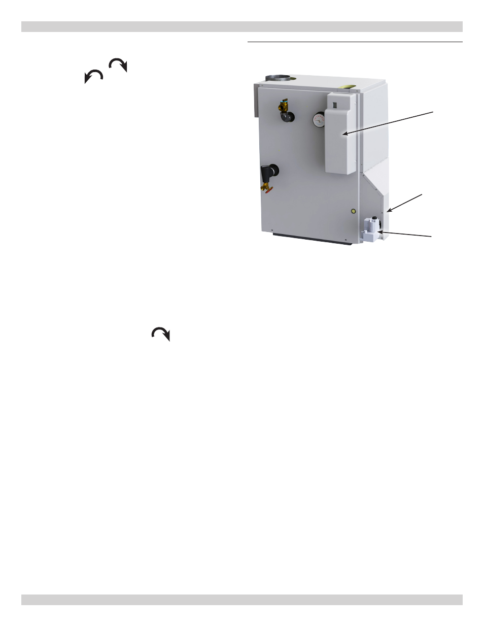
Front Lower
Jacket Panel
High Limit
Control
Gas Valve
15 - CHECKING GAS INPUT RATE TO BOILER
Figure 19
- Boiler Right Side and Front