OWON ODP Series User Manual
Page 14
4.Quick Start
9
②
③
④
⑤
⑥
⑦
⑧
⑨
⑩
⑪
①
⑫
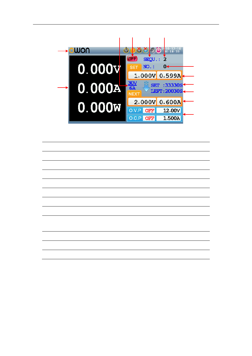
Figure 4-4 User interface in Parallel/Series mode
① Maximum ratings of voltage and current
② Channel status
③ Output mode of timing output (Sequence / Loop)
④ Timer range
⑤ The parameter number of the current output when the timing output is on
⑥ Specified values of voltage and current
⑦ Specified time of current output when the timing output of is on
⑧ Left time of current output when the timing output of is on
⑨ Specified values of voltage and current that will be output at the next fixed
times when the timing output of is on
⑩ Status and set values of O.V.P and O.C.P in current status
⑪ Actual output values of voltage , current and power
⑫ Status icons, see "Status Icons" on P10 for more details
Plus-minus Mode