Description, Mounting, Page – Orion System OE217-00 User Manual
Page 36: Sensor with remote pickup
Form: AAON-OE256-07-EBUS-DUCT-CO2-1B.doc
Page
1 of 1
Description
The E-BUS Duct Mounted E-BUS CO
2
Sensor
with Remote Pickup (Orion Part No. OE256-07;
AAON Part No. V09320) is used in conjunction
with the VCB-X Controller (Orion Part No. OE335-
23-VCB-X; AAON Part No. V04740) to monitor
and control Return Air CO
2
levels in the building
environment.
Some typical applications are:
Demand Control Ventilation
Controlling ventilation in a building where
the occupancy varies frequently
Controlling ventilation based on CO
2
levels to ensure excess outdoor air is not
causing energy waste
To ensure good air distribution throughout
building zones
The OE256-07 is used for monitoring duct CO
2
levels and is designed for permanent mounting in
the Return Air duct. It utilizes an aspiration box to
accurately capture CO
2
levels in the duct. It con-
nects to the VCB-X by using an E-BUS cable with
E-BUS connectors.
The OE256-07 CO
2
Sensor uses non-dispersive
infrared (NDIR) technology and has a measure-
ment range of 0-2000 ppm.
Mounting
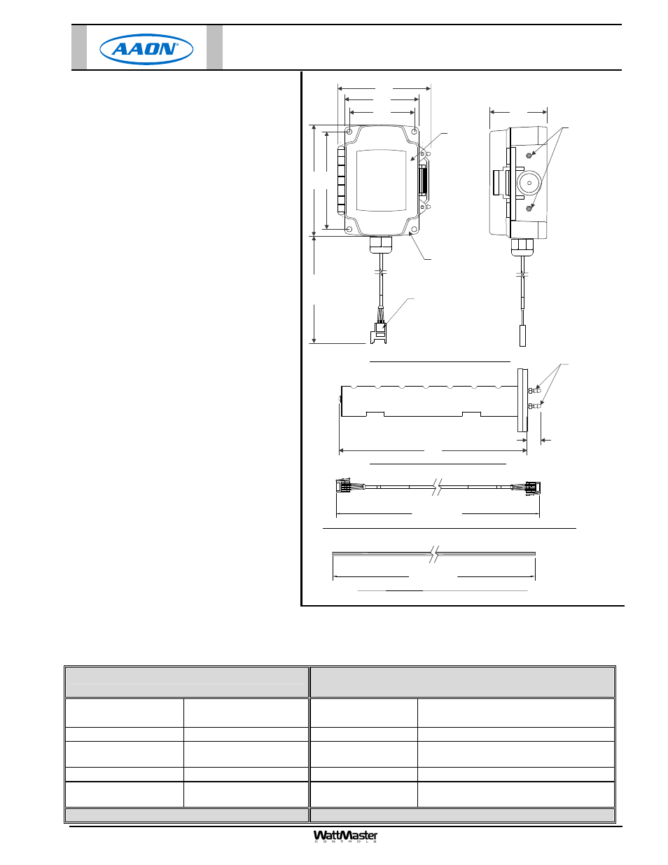
The OE256-07 CO
2
Sensor is housed in an aspira-
tion box. A conduit clamp is provided to help seal
the opening where the sensor cabling penetrates
the aspiration box housing. The sensor has a Jack
E-BUS connector for connecting it to the provided
EBC E-BUS cable. The EBC E-BUS Cable con-
nects to the VCB-X Controller or E-BUS Hub or
Adapter Board and then to the VCB-X Controller.
The sensor and aspiration box assembly is
mounted and secured to the ductwork with the (2)
supplied sheet metal screws. The remote pickup
tube assembly is mounted separately to the duct-
work by first cutting a 1
1
/
4
” diameter hole in the
ductwork wall. The remote pickup tube is then in-
serted into the hole. The remote pickup tube is then secured to the ductwork by inserting (2) supplied sheet metal screws
through the (2) mounting holes in the remote pickup tube mounting plate and securing the remote pickup tube assembly by
screwing it to the ductwork using a manual or powered screw driver to tighten the screws. Using the supplied 10 ft. long tub-
ing, connect the remote pickup tube to the aspiration box assembly, cutting the tubing to fit.
4
3
2
1
3M
E-BUS CONNECTOR
FEMALE END
SENSOR
HOUSING
HINGED
COVER
BRASS BARB
FITTINGS FOR
0.170 I.D. TUBING
BRASS BARB
FITTINGS FOR
0.170 I.D. TUBING
EBC-10F
"WATTMASTER EBUS"
"WATTMASTER EBUS"
EBC-10F
43
2
1
3M
432
1
3M
120.00” APPROX.
120.00” APPROX.
E-BUS CONNECTOR EXTENSION CABLE WITH MALE ENDS (PROVIDED WITH SENSOR)
0.170 I.D.
TUBING (PROVIDED WITH SENSOR)
FIRE RATED
CO2 PICKUP TUBE (PROVIDED WITH SENSOR)
CO2 SENSOR, HOUSING AND CABLE ASSEMBLY
5.
00
"
3.31"
4.12"
2.55”
13
.00
"
APPROX.
8.25"
0.55”
4.
06
"
2.81”
Technical Data
OE256-07 E-BUS Duct Mounted CO
2
Sensor
with Remote Pickup
Input Power
12-34 VDC
Power Consumption
30 mW Maximum Average
1.25 W Peak Power
Operating Temperature
14
to 122F Operating Humidity
5-95% RH Non-Condensing
Sample Method
Flow-Through
50-100 ml/min
Measurement Range
0 to 2000 ppm
Sensitivity
<
20 ppm Resolution
1 ppm
Accuracy
50 ppm @ 1000 ppm or
2% measured value
Communications E-BUS
One Year Warranty
WattMaster reserves the right to change specifications without notice
OE256-07 E-BUS Duct Mounted CO
2
Sensor
with Remote Pickup