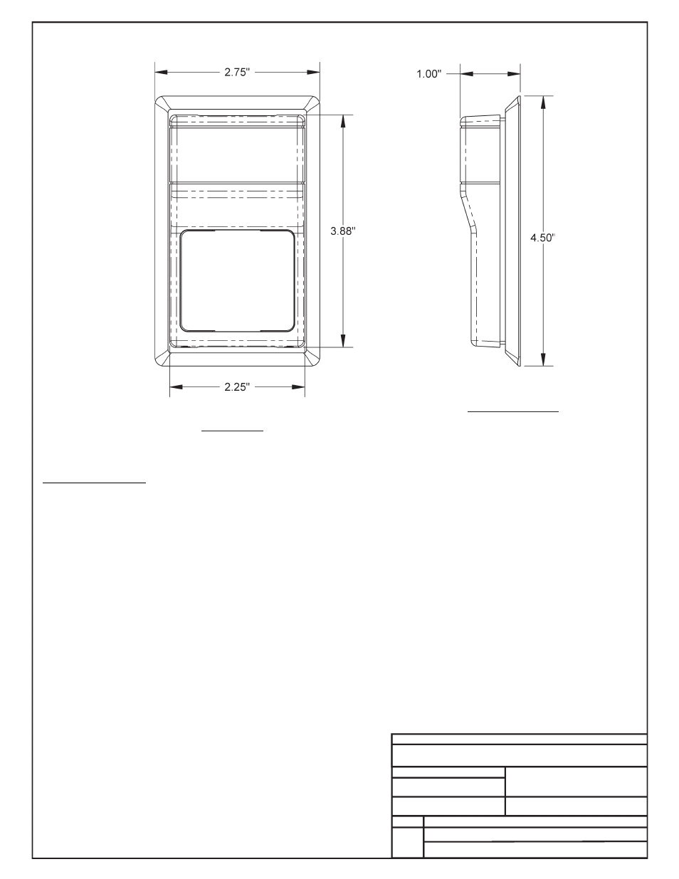
Front view right side view – Orion System OE217-00 User Manual
Page 22
JOB NAME
FILE NAME
G-OE265-11-SPHUMID1D.PDF
DATE: 08/02/07
PAGE
DESCRIPTION
OE265-11
Space Humidity Sensor – 0-5 VDC
DRAWN BY: B. CREWS
Notes:
1.) The sensor is designed to be wall
mounted in rooms where appearance is
important. It may be mounted directly on
dry wall or on any single gang electrical
outlet box with no adapters required.
Toggle bolts or other direct wall mount
screws can be used where conduit is not
required. It includes a detachable
mounting plate. The cover is secured with
tamper-resistant hex screws. The sensor
should be mounted approximately five feet
above the floor, on an interior wall, away
from any heating or cooling generating
devices, and out of the sun. Plug the
wireway hole to prevent false readings by
air drafts within the wall.
2.) All Wiring To Be In
Accordance With Local
And National Electrical
Codes And Specifications.
1 of 2
Installation Instructions:
1.) Place The SpaceHumidity Sensor Where It Is To Be Mounted. See Note 1 Below For Important Mounting Information And Considerations.
2.) Remove The Humidity Sensor Cover By Screwing In The 2 Allen Screws That Secure It To The Base.
3.) Connect All Of The Wires From The Controller Board To The Corresponding Terminal Blocks Per The Wiring Diagram On Page 2 Of This Drawing.
4.) Secure The Cover Onto The Base Housing By Snapping The Cover Onto The Base And Backing Out The 2 Allen Screws.
5.) Verify That You Are Getting A Humidity Reading On Your Control System. Please Note That It May Take Ten To Twenty Minutes For The Sensor
Reading To Stabilize Upon Initial Power Up.
Front View
Right Side View