Gpc-xp controller screens, Unit selection and analog inputs – Orion System System Manager TS II For GPC-XP User Manual
Page 13
SMTS II for GPC-XP Technical Guide
GPC-XP CONTROLLER SCREENS
13
Unit Selection and Analog Inputs
My System Unit Selection
From the Main Screen, touch the
< My System>
icon.
The Selected Unit Screen will appear. See Figure 13.
NOTE:
If you have chosen the One to One Unit Connection
in the System Manager Settings Screen, this screen
(Figure 13) will not appear. Instead, the unit’s fi rst
Status Screen
will appear.
Back
Selected Unit [Loop 1 - Unit 1]
1
GO
0
1
0
-
-
-
-
+
+
+
+
Figure 13: Unit Selection Screen
In Figure 13, Loop 1 and Unit 1 are selected as indicated in the fi gure
with white text. They also appear in the Top Menu Bar in brackets.
Use the
<+>
and
<->
buttons to move up and down through the loops
and units. Enter the desired Loop # and Unit # and then touch
to access the unit’s Status Screen.
Viewing / Confi guring GPC-XP Status
Screens
Figures 14-27 depict the GPC-XP Status Screens and corresponding
data entry screens associated with them
. Notice that the controller
is identifi ed by loop number and unit number - in this case, 0001
represents Unit 1 with a stand-alone connection.
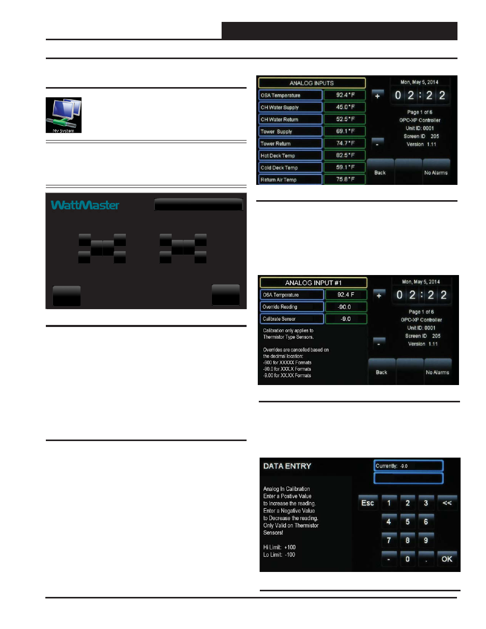
Figure 14: Analog Inputs Screen
While in each Status Screen, touch the
<+>
and
<->
buttons to view
more status screens. These screens roll back to the fi rst Status Screen.
Figure 15: Analog Input Details Screen
Analog Inputs:
Thermistor sensors can be calibrated and all read-
ings can be overridden to specifi c values by Level 3 users. To do
this, while in the Analog Input Screen, touch the value fi eld for the
sensor you would like to calibrate or override.
In this example below (Figure 15), Analog Input #1 - OSA Tem-
perature Sensor is selected.
Calibrate Sensor:
To calibrate a thermistor sensor, touch the Cali-
brate Sensor value fi eld. The Data Entry Screen will appear. Type a
positive value to increase the reading or a negative value to decrease
the reading. High Limit: +100. Low Limit: -100. Press
to save.
Figure 16: Calibrate Sensor Data Entry Screen