Installation & wiring, Sa controller technical guide 32, Two condenser head pressure module – Orion System SA Controller User Manual
Page 32: Zone
Zone
Zone
Installation & Wiring
SA Controller Technical Guide
32
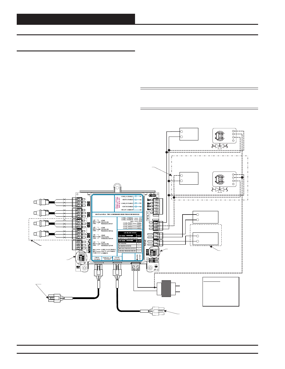
Two Condenser Head Pressure Module Overview and Wiring
Two Condenser Head Pressure Module
The Two Condenser Head Pressure Module ( OE370-23-HP2C) monitors
four individual head pressure transducers and controls two Condenser
Fans or Water Valves on units with two physically separate condenser
sections. The highest reading of head pressure transducers 1 & 2 controls
Condenser Signal A. The highest reading of head pressure transducers
3 & 4 controls Condenser Signal B.
A pulse width modulation (PWM)
signal is used to control the Condenser Fans. A 0-10 volt output signal
is used to control the valves.
The Two Condenser Head Pressure Module is connected to the SA
Controller ( OE332-23-SA) using the E-BUS Distribution Module
(OE365-23-EBD-A). This allows the Two Condenser Head Pressure
Module to receive setpoints from the SA Controller. See Figure 27
below for wiring diagram.
The Two Condenser Head Pressure Module requires a 24 VAC power
connection with an appropriate VA rating.
NOTE: For complete information, including the sequence of
operation, refer to the Two Condenser Head Pressure Module
Technical Guide.
Figure 27: Two Condenser Head Pressure Module to E-BUS Distribution Module Wiring Diagram
SIG
GND
+V
BK
RD
WH
SIG
GND
+V
BK
RD
WH
SIG
GND
+V
BK
RD
WH
SIG
GND
+V
BK
RD
WH
COM
Condenser Fan A
ECM Motor
+
Head Pressure Transducers
0 - 667 PSI
(One Per Refrigerant Circuit)
OE370-23-HP2C
Two Condenser Head Pressure Module
Setting Of OPTIONS
Dip Switch
Not Required When
Used With SA Controller
+5V
SIG 2
GND
OP
T
IO
N
S
ALARM
ANALOG
STAT
+5V
COMM
GND
SIG 4
GND
BIN 2
R1
R2
GND
RELAYS
ADDRESS
SIG 3
+5V
GND
BIN 1
COM
+5V
SIG 1
R3
R4
Rc
AO1
AO2
PWM1-
PWM1+
PWM2-
PWM2+
This Dip Switch Is Not
Used For This Application
PWR
COM
Condenser Fan B
ECM Motor
+
COM
COM
+
+
VFD Condenser A Signal
For Air Cooled
Condenser Applications
VFD Condenser B Signal
For Air Cooled
Condenser Applications
Head Pressure Control
Valve Actuator - A
For Water Cooled
Condenser Applications
Head Pressure Control
Valve Actuator - B
For Water Cooled
Condenser Applications
Connect To E-BUS
Distribution Module
Connect To Other
WattMaster-Approved
E-BUS Expansion Module(s)
HSSC Cable
24 VAC Transformer
3 VA Minimum
Line Voltage
24 V
A
C
GND
WARNING!!
Observe Polarity! All
Boards Must Be Wired
With GND-to-GND And
24 VAC-To-24 VAC.
Failure To Observe
Polarity Could Result In
Damage To The Boards.
HSSC Cable
Use For Dual
Applications Only
Use For
Dual
Applications
Only
Use For
Dual
Applications
Only
3 (Y)
3 (Y)
5 (U)
5 (U)
2 (+)
2 (+)
1 (-)
1 (-)
Revised 1/21/11