Montigo 36DRG User Manual
Page 6
Page 6 of 11
36DRG
09/96
13.) a) Operating the fan:
The fan speed can be controlled by turning the
variable speed control clockwise to slow the fan
down and counterclockwise to speed it up.
There is a built-in automatic heat control that will
Activate when the fireplace has reached (100 F)
temperature. The fan will not operate when the
fireplace is cold.
b)Removing fan assembly for servicing:
Remove the (3) screws located on each side wing
of the fan bracket. Remove the (3) screws
located on the base of the bracket. Back out
the (2) levelling bolts also located on the box.
Remove. (See Drawing #6)
14.) Connect gas to burner using the flexible gas line
extension provided with the fireplace.
CAREFULLY TEST TO ENSURE THAT
THERE ARE NO LEAKS USING A SOAP SUDS
SOLUTION. UNDER NO CONDITION SHALL
FLAME OR FIRE BE USED TO LOCATE A
GAS LEAK.
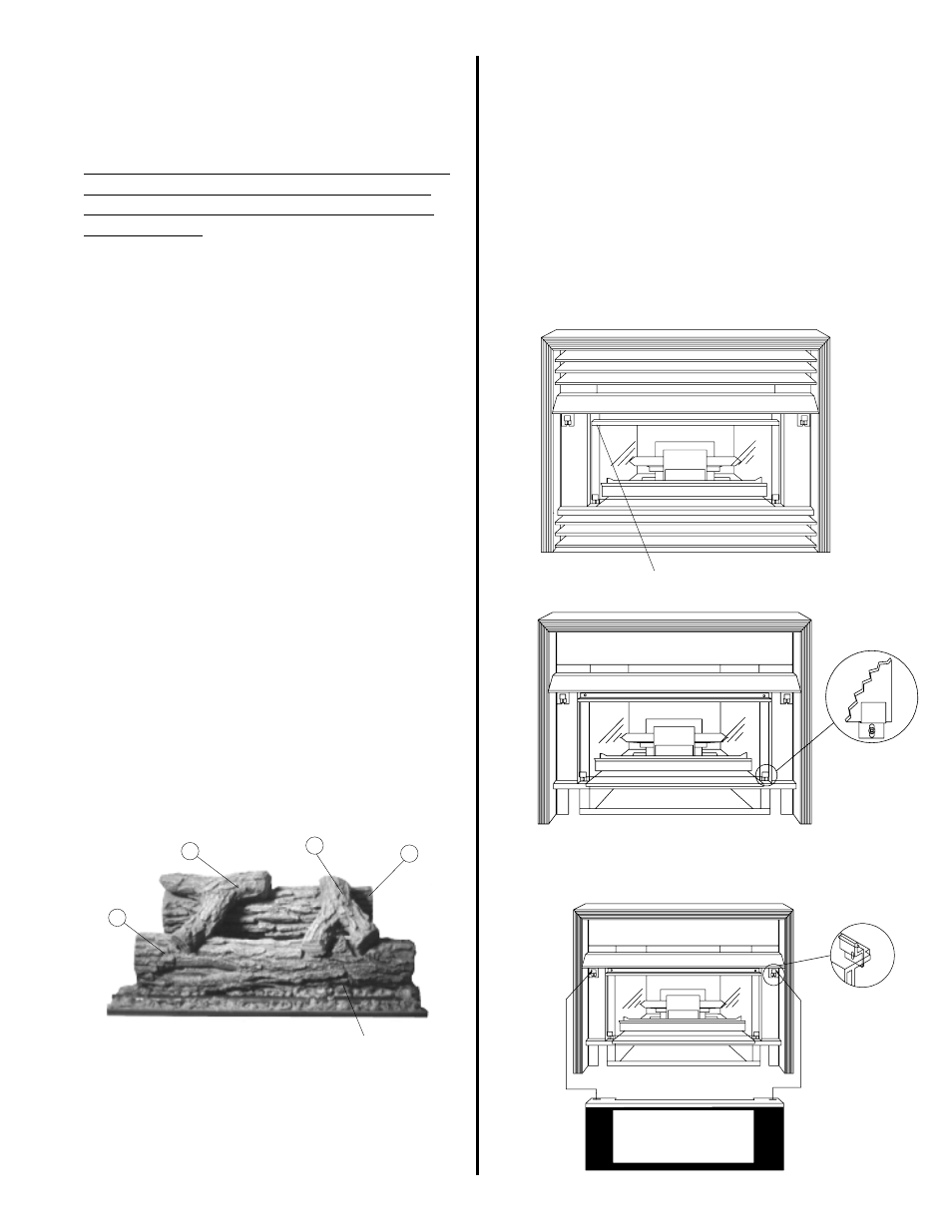
15.) Install the log set:
Place log “A” on the log rest at the REAR of the
firebox.
Place log “B” on the log rest at the FRONT of the
firebox.
Place log “C” on top of logs A & B on the right
hand side.
Place log “D” on top of logs A & B on the left
hand side.
WARNING: FAILURE TO INSTALL LOGS AS PER
INSTRUCTIONS WILL RESULT IN EXCESSIVE
SOOTING.
16.) Ember Placement:
Distribute evenly alongside the front burner only.
Do not pile material directly on top of burner
ports.
B
D
C
A
Glowing Embers
GLASS REMOVAL / PLACEMENT
Inside Piece
Only
Slide glass under
metal strip
Secure clips to
hold glass in
place
CAUTION: IMPROPER PLACEMENT OF EMBERS
COULD RESULT IN THE FLAME BEING
DIVERTED TOWARDS THE GLASS CAUSING
MARKS TO FORM
17.) Glass Placement:
This appliance has two pieces of glass. The
smaller sized glass will be placed on the unit first.
Place top of glass behind metal strip. Set bottom
of glass in place and secure with clips provided.
Mount the front piece of glass on the brackets
Provided underneath the decorative hood piece.
DRAWING #9c
DRAWING #9b
DRAWING #9a