Montigo 36DRG User Manual
Page 5
Page 5 of 11
36DRG
09/96
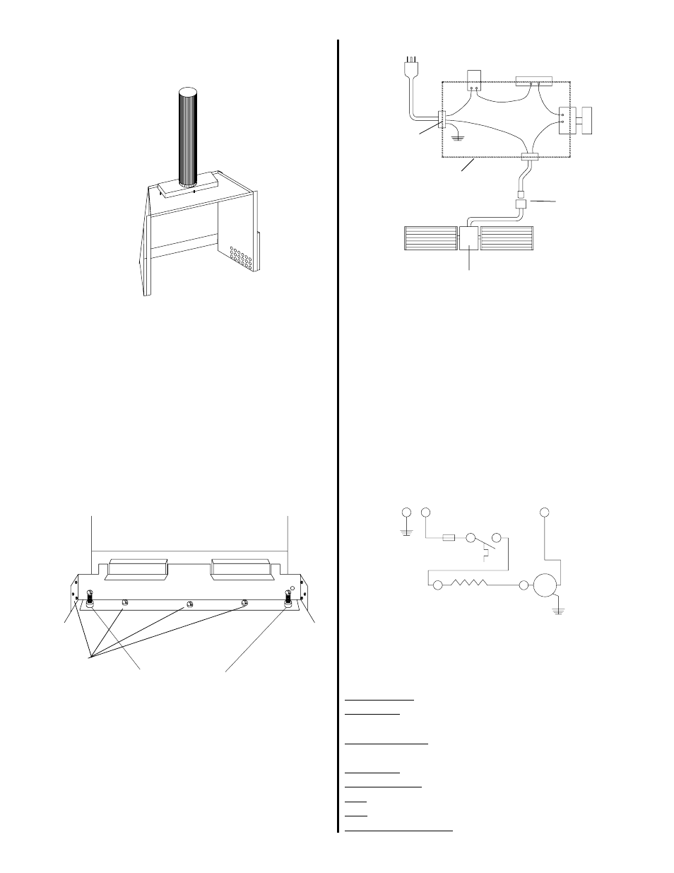
8.) Push the drafthood back in to place and re-secure.
DRAWING #5
9.) Level the unit by adjusting the two hex head
machine screws located inside the shell.
For easiest access, adjust these screws prior to
replacing the heat exchanger. If further adjustments
need to be made to level the unit after the heat ex-
changer has been replaced, locate the levelling bolts
behind the gas control. The Piezo ignitor and mount-
ing bracket will have to be removed to reach the bolt
on the right hand side. BE SURE TO MAKE ALL
ADJUSTMENTS PRIOR TO CONNECTING THE
GAS LINE.
FAN BRACKET
Levelling Bolts
10.) Once the outer shell and heat exchanger have
been secured together, re-install the burner tray and
rheostat box.
11.) Connect the fan wires to the rheostat and extend
the electrical cord along the hearth to wall outlet or
direct wire to grounded 120V supply.
BK
G
(FAN SWITCH)
AUTOMATIC HEAT CONTROL
(100 F)
2 AMP FUSE
WH
BK
BK
BK
BLOWER
BLOWER
MOTOR
STRAIN RELIEF
QUICK CONNECT
PLUG TO MOTOR
RHEOSTAT CONNECTION
MOTOR
FAN SWITCH
G
H
N
FUSE
SCHEMATIC DIAGRAM
VARIABLE
SPEED
CONTROL
Remove to
access fan
COMPONENTS:
Blower/Motor: Fasco; dual squirrel case blowers
Fan Switch: T-O-D 60T12; 115 V; 60HZ; 100 F setting;
enclosed disk
Wiring (Internal): Type TEW 105C or equivalent; 18
AWG
Connectors: Suitable solderless connectors, CSA Listed
Appliance Cord: Wire Fab; SPT-2; 3 Cond
Plug: 18 Ga (CSA), moulded plug
Fuse: 2 Amp; buss type or equivalent
Pilot Burner & Ignitor: Robertshaw 5SHL2
NOTE: If any of the original wire as supplied with the
appliance must be replaced, it must be replaced with type
SEW wire or its equivalent.
DRAWING #8
12.) Test fan for proper operation.
WARNING: ELECTRICAL GROUNDING
INSTRUCTION:
The appliance must be electrically connected and
grounded in accordance with local codes or, in the
absence of local codes, with the current CSA C22.1
Canadian Electrical Code. The fan is equipped with
a three prong (grounding) plug for your protection
against shock hazard and should be plugged directly
into a properly grounded three prong receptacle. Do
not cut or remove the grounding prong from this
plug.
DRAWING #7
JUNCTION BOX