Section 3: finishing, Installation – Montigo R324-ST User Manual
Page 8
R324-STIO Indoor Outdoor Ventless Gas Fireplace
Page 8
XG0775 - 150204.1
Installation
Section 3: Finishing
FINISHINGTHEUNITONTHEEXTERIOROFTHEBUILDING:
STEP1:Select a location such that the fireplace floor maintains a 10"
clearance above grade (see Fig. 4d). The power vent module will expel
high temperature flue gases through the louvers. When selecting the
material for the hearth please keep in mind the potential for discoloration
due to high temperatures.
STEP2:Determine where the unit will be placed in relation to the exterior
wall. Position flashing such that it will be flush to the exterior wall when
installed.
STEP3:Attach the flashing provided to the fireplace exterior using the
sheet metal screws provided. (see Fig.4) Apply a bead of silicone to the
back of the flashing to ensure a proper seal.
(Please note: You may drill a 1/8" starter hole into the outside skin of the
fireplace using the cobalt drill bit provided in your flashing kit.)
STEP4:Slide the unit in place into the intended location from the outside of
the building until the flashing is flush with the building exterior. (See Fig. 4a)
Nail the flashing to the exterior sheathing of the building
STEP 5: Cover the flashing with approved waterproofing membrane
brought to the 1/2" edge of the unit (See Fig. 4b).
STEP6:Install steel stud construction (or other non-combustible) to
create 1/2" clearance on sides and 3" clearance on top before installing
finishing materials. (See. 4c)
(Please note: Ensure that all materials installed on the face of the unit
provide adequate clearance to allow the removal of door and louvers as
required.)
MAINTAIN CLEARANCE of 1/2" on sides and 3" on top TO ALL
COMBUSTIBLEMATERIALSFROMTHEUNITONSIDES,TOPAND
FACEOFTHEUNIT
STEP7:Cover face, framed sides and framed top with material of your
choosing.
ENSURE THERE IS NO OBSTRUCTION IN FRONT OF THE LOUVERS
AT ANYTIME AS THIS MAY RESULT IN THE POWER VENT MOTOR
OVERHEATING.
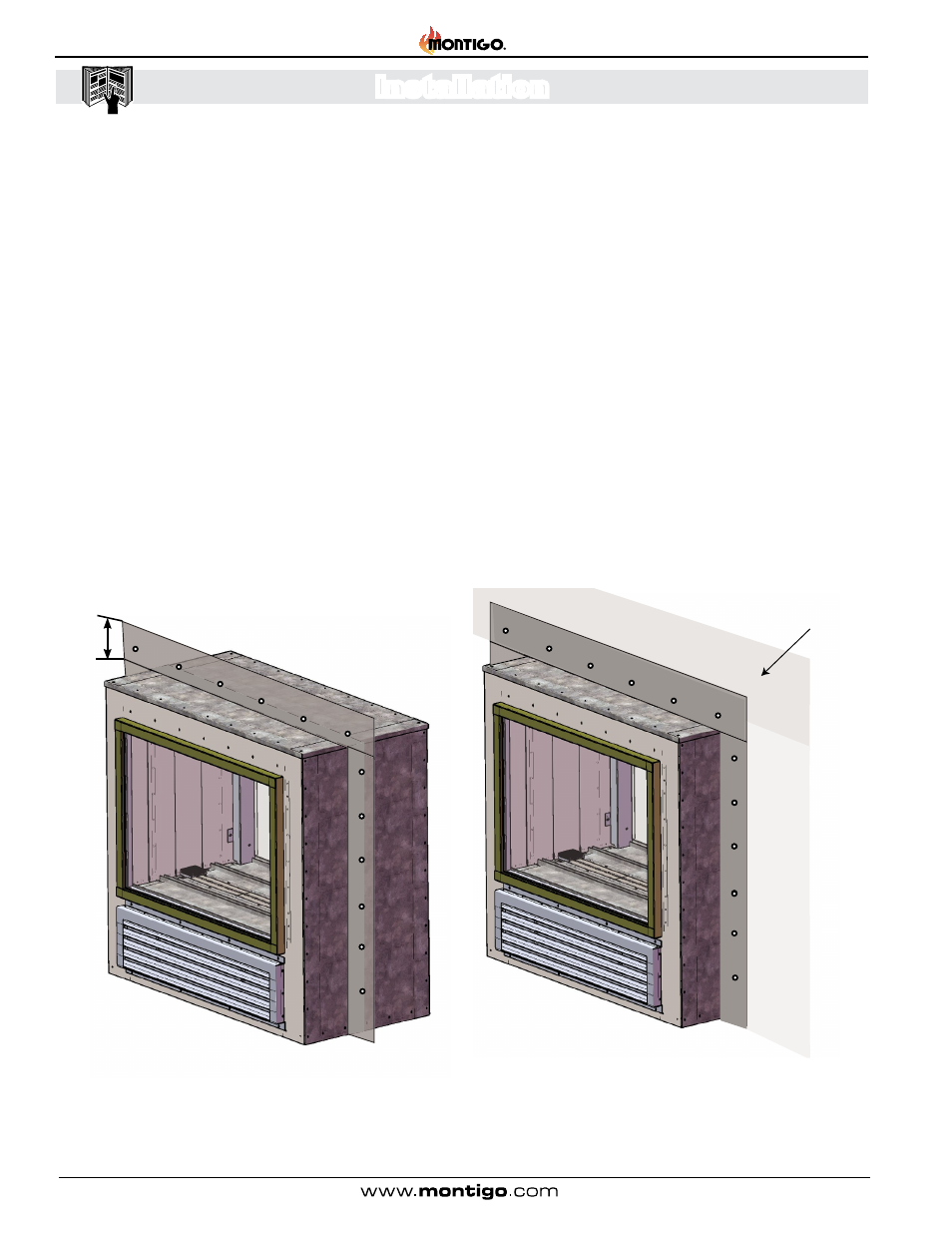
Figure 4a: Slide unit into place from the outside of the building until
the flashing is flush to the exterior wall
6”
Exterior Building Wall
Figure 4: Attach flashing to unit using sheet metal screws provided,
apply a bead of silicone to flashing where it meets the unit