Installation, Chimney liner installation – Montigo DHS User Manual
Page 8
Page 8
Hotshot Gas Fireplace Insert
XG0511 - 150203
Installation
Chimney Liner Installation
This appliance is for installation with 4" diameter Type-B gas vent
(B-Vent) or double wall aluminium flex liner.
Install flex liner or B-Vent inside the masonry chimney all the
way to the top of the chimney cap. Vertical vent height must be a
minimum of 12 feet from the bottom of the fireplace to the bottom
of the termination (See Figure 4.)
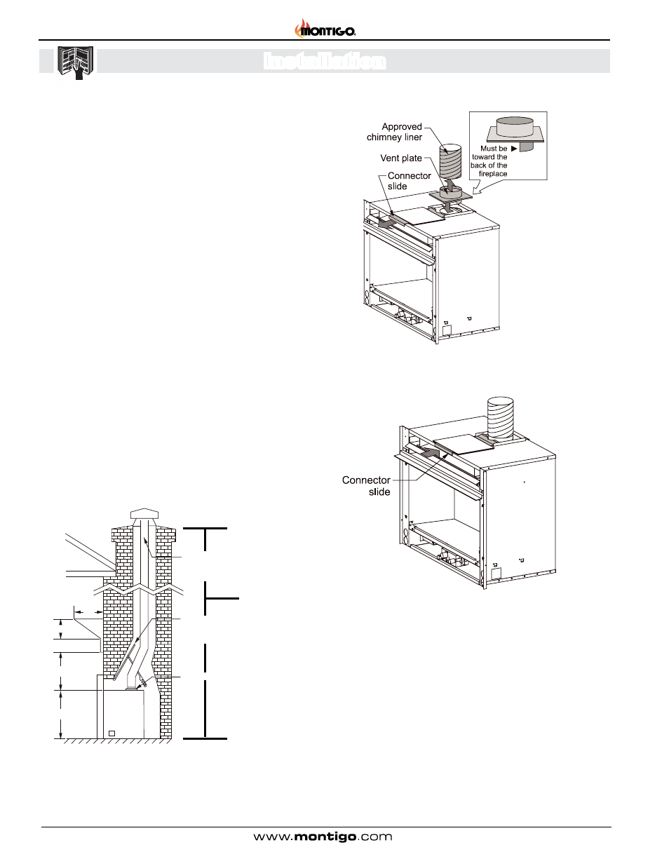
Use the vent plate (supplied with the Hotshot) to connect the
chimney liner to the insert. Slide the flex over the vent plate and
attach with two sheet metal screws. Make sure the flange on the
bottom of the vent plate is toward the back of the fireplace. See
figure 5a.
Slide the Hotshot as far back as possible into the fireplace open-
ing. Reach inside the opening above the Hotshot and insert the
vent connector into the slot at the back of the fireplace. Push the
connector slide back as far as it will go to secure the chimney liner
in position. See figure 5b.
Centre the Hotshot in the fireplace opening, and connect the gas
line. (See Figure 3).
To install the face plate and louvres, see Installing Face Plate &
Trims.
All installations must conform with local codes. In the absence of local
codes, installations must conform with the most recent version of the
National Fuel Gas Code (ANSI Z223.1-1988) or the Gas Installation
Code (CAN/CGA B149.1 and .2).
10
4” Flex liner
installed to
top of chimney
Damper plate
locked in
“open” position
Vent connector
8
8
20
2 ½
Minimum 12 ft
Figure 4. Installation requirements and mantle clearances.
Figure 5a. Connecting the chimney liner to the vent plate.
Figure 5b. Securing the chimney using the connector slide.