Maintenance, Removing the log grate, Removing the refractory – Montigo H36PVN User Manual
Page 30
H36PVN Power Vent Indoor Gas Fireplace
Page 30
XG0649 - 031511
Maintenance
1
2
Removing the Log Grate:
The
H36PVN is supplied with a log Grate that is fastened directly to
the base of the Fireplace . To remove the Grate, to perform certain
Maintenance functions, follow the steps described below:
Step 1. CLOSE GAS VALVE AT INCOMING TO FIREPLACE, (By
Qualified Persons ONLY, See 'Before You Start' in the Index).
Step 2. Remove the two (2) machine screws that hold the Pilot
Assembly in place, Figure 20 . (Philips head screwdriver required).
Figure 20. (Pilot mounting machine screws).
3
Step 3 & 4 Remove the two (2) (RH & LH) Base mounting machine
screws, Figure 20a & 20b . (Philips head screwdriver required).
Figure 20a. (LH Base mounting
machine screw).
4
Step 5. Loosen, and Remove the Flexible Gas hose (at fitting),
(turn clockwise, left to right) Figure 20c & 20d . (3/4" Open end
wrench required).
5
5
Figure 20b. (RH Base mounting
machine screw).
5
1
2
3
4
Figure 20c. (Gas fitting).
NOTE: Ensure all 5-steps are complete before removing Log Grate.
(Failing to do so may damage the flexible gas hose, or mounting
hardware of the grate).
Figure 14e.
Figure 20d. (Loosening Gas fitting
on burner).
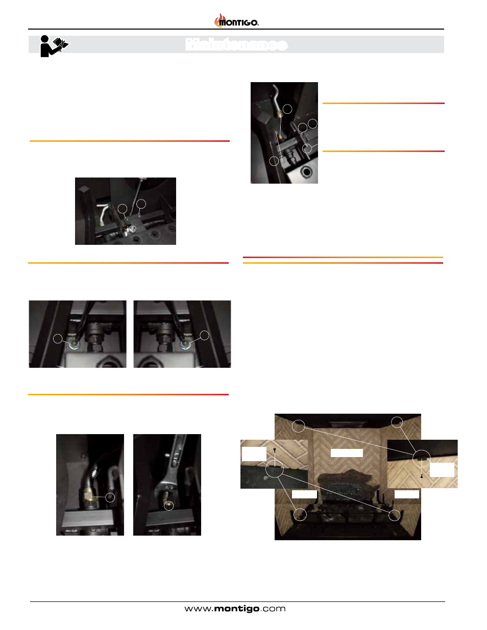
Removing the Refractory:
The
H36PVN is supplied three (3) pieces of firebox refractory Lining .
These panels are fastened directly to the interior sides, and back
of the Fireplace firebox with brackets . To remove the brackets and
panels follow the steps described below:
Step 1. Remove the RH-TOP machine screw that hold the Side
Refractory panel in place, then the bottom, Figure 22 . (Philips head
screwdriver required).
Step 2. Remove the RH-Refractory panel from the firebox, Figure
22 . (Place the Refractory panel somewhere safe where it will not
get chipped or damaged).
Step 3. Follow step1 & 2 to remove the LH-Side Refractory panel,
Figure 22 . (Philips head screwdriver required).
Figure 20e. (Log Grate Removal Sequence).
Figure 22. (Removing Refractory panels).
Step 1 & 2. Figure 20. (Pilot mounting
machine screws).
Step 3 & 4. Figure 20a. (LH Base
mounting machine screw).
Figure
20b. (RH Base mounting machine
screw).
Step 5. Figure 20c & 20d . Loosen, and
Remove the Flexible Gas hose (at
fitting), (turn clockwise, left to right)
(
3/4" Open end wrench required).
LH-Panel
RH-Panel
Back-Panel
Bottom
Brackets
Top
Brackets