1 introduction, Pcm-dac02 – Measurement Computing PCM-DAC02 User Manual
Page 5
1 INTRODUCTION
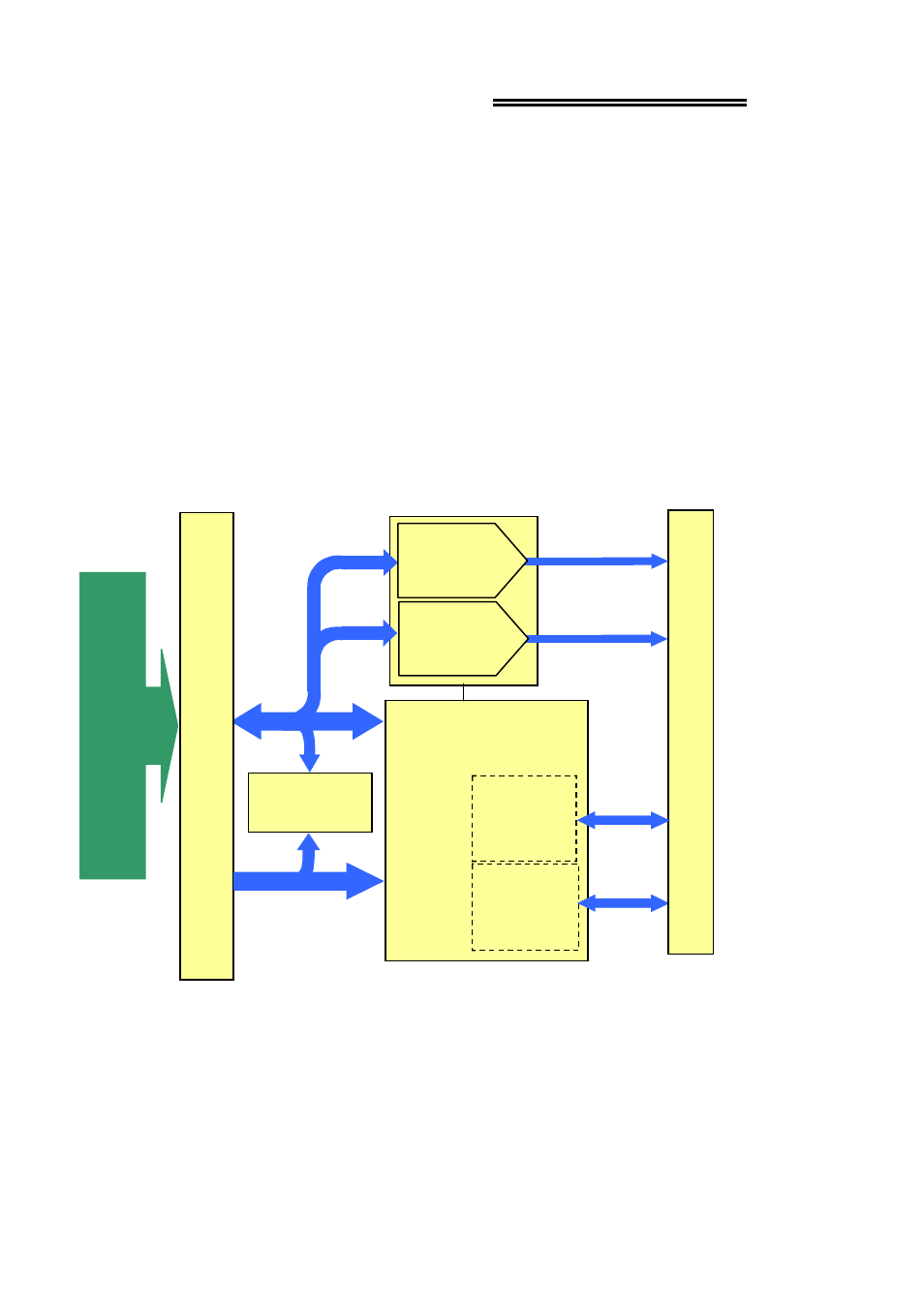
The PCM-DAC02 is an analog output control board for IBM PC compatible
computers with PCMCIA type slots. The heart of the board is a dual 12-bit digital-to-
analog converter. Analog voltage signals are generated by the D/A from registers.
Control of I/O operations is done by the Field Programmable Gate Array (FPGA) on
the board (Figure 1-1). Double-buffering of the output registers permit simultaneous
output changes.
Ranges of the two analog outputs are individually programmable for bipolar ±5V or
±10V, or unipolar 0 to 5V or 0 to 10V.
Eight bi-directional digital I/O lines arranged in two, 4-bit ports provide the capability
of sensing and controlling discrete events. The ports can be programmed to be eight
inputs, eight outputs, or four inputs and four outputs.
Figure 1-1. PCM-DAC02 Block Diagram
1
PC
MCI
A
BUS
C
O
NNE
CT
OR P1
(
68
-P
IN
)
ADDRESS
BUS
H
O
ST
BU
S
AD
A
P
T
ER
CONTROLLER
FPGA
D/A
CONVERTER
12-BIT
P2
C
O
NN
ECT
O
R
(1
5
PIN
)
PCM-DAC02
DIGITAL
I/O
PORT
4 BITS
DIGITAL
I/O
PORT
4 BITS
ATTRIBUTE
MEMORY
DATA
BUS
D/A
CONVERTER
12-BIT