Counters, Power consumption, Environmental – Measurement Computing CIO-DAS1401/12 User Manual
Page 17: Main connector and pin out
CIO-DAS1401/12User's Guide
Specifications
17
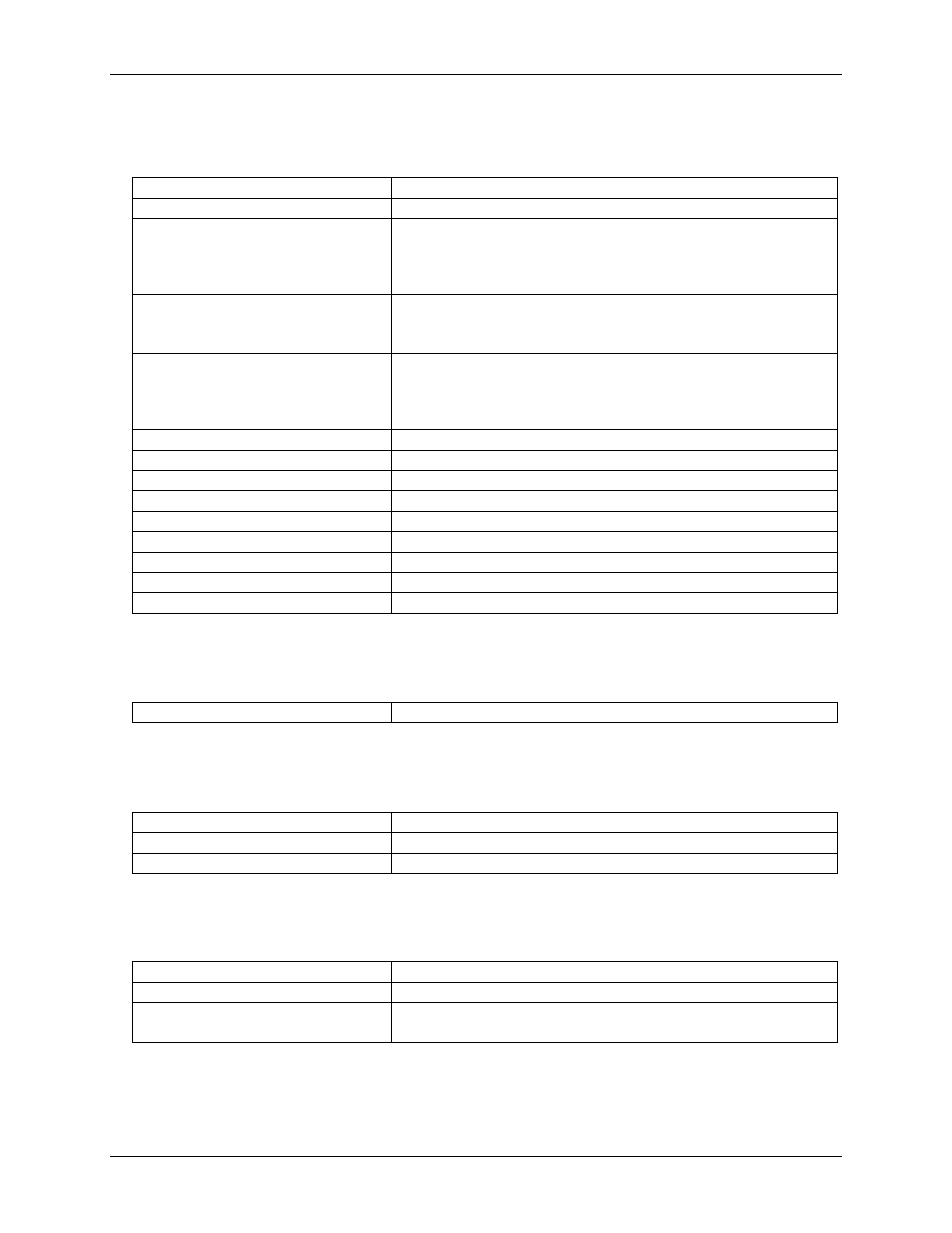
Counters
Table 3. Counter specifications
Counter type
82C54
Configuration
3 down counters, 16-bits each
Counter 0 — Independent, user
configurable
Source:
Programmable - Internal 100 kHz or external (CTR0
Clock)
Gate:
External (DIN2)
Output:
Available at user connector (CTR0 Out)
Counter 1 — ADC Pacer Lower Divider
Source:
1 or 10 MHz oscillator (jumper selectable)
Gate:
Tied to CTR2 Gate, programmable source.
Output:
Chained to CTR2 Clock.
Counter 2 — ADC Pacer Upper Divider
Source:
CTR1 Out
Gate:
Tied to CTR1 Gate, programmable source.
Output:
Programmable as ADC Pacer clock, hardwired to user
connector (CTR2 Out)
Clock input frequency
10 MHz max
High pulse width (clock input)
30 ns min
Low pulse width (clock input)
50 ns min
Gate width high
50 ns min
Gate width low
50 ns min
Input low voltage
0.8 V max
Input high voltage
2.0 V min
Output low voltage
0.4 V max
Output high voltage
3.0 V min
Power consumption
Table 4. Power consumption specifications
+5 V
1.4 A typical, 2.1 A max
Environmental
Table 5. Environmental specifications
Operating temperature range
0 to 50 °C
Storage temperature range
-20 to 70 °C
Humidity
0 to 90% non-condensing
Main connector and pin out
Table 6. Main connector specifications
Connector type
37-pin D type connector
Compatible cable
C37FF-x
Compatible accessory products with the
C37FF-x cable
CIO-MINI37
CIO-SSH-16