Functional details, Auxiliary trigger, Burst mode generator – Measurement Computing CIO-DAS1401/12 User Manual
Page 14: Calibration and test, Required equipment
14
Chapter 3
Functional Details
Auxiliary trigger
There is a position for a header connector at the rear of the CIO-DAS1401/12. This connector provides the
same function as that found on the DAS-1600.
The A/D trigger signal may come from this connector, if installed. A jumper controls which pin the trigger
signal comes in from. We do not install this connector (nor is it installed on the DAS-1600).
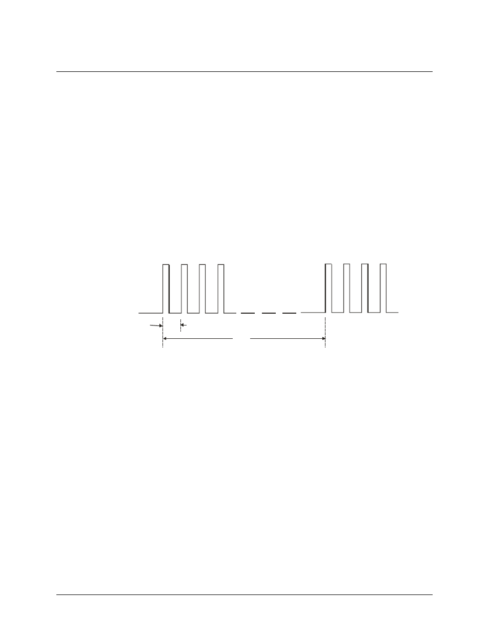
Burst mode generator
The burst mode generator is a clock signal that paces the A/D at the maximum multi-channel sample rate, and
periodically performs additional maximum-rate scans. In this way, the channel-to-channel skew (time between
successive samples in a scan) are minimized without taking a large number of undesired samples (see Figure 8).
Ch0 Ch1 Ch2 Ch3
Ch0 Ch1 Ch2 Ch3
4 S
µ
Delay
Burst mode pacer
is fixed at 4 S
µ
The length of the delay between
bursts is set by one of the internal
counters or may be controlled via
external trigger.
Figure 8. Burst mode generator timing
The CIO-DAS1401/12 burst mode generator takes advantage of the fast A/D. The burst mode skew is 4 µs.
Calibration and test
Every board is fully tested and calibrated before shipment. For normal environments, a calibration interval of
six months to one year is recommended. If frequent variations in temperature or humidity are common,
recalibrate with InstaCal at least every three months. It takes less than 20 minutes to calibrate the CIO-
DAS1401/12.
Required equipment
Ideally, you will need a precision voltage source, or a non precision source and a 4½ digit digital voltmeter, and
a few pieces of wire.
You do not need an extender card to calibrate the board, but you do need to remove the cover from your
computer to adjust trim pots during calibration.