Installing the cio-das1401/12, Connecting the board for i/o operations, Connectors, cables – main i/o connector – Measurement Computing CIO-DAS1401/12 User Manual
Page 12
CIO-DAS1401/12User's Guide
Installing the CIO-DAS1401/12
12
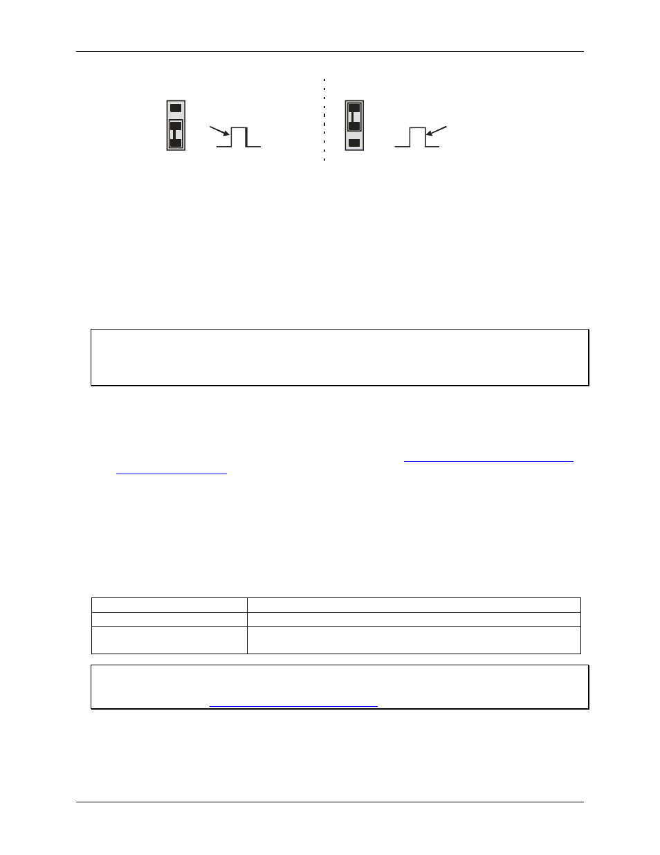
Falling edge A/D trigger
DAS-1600 method
J9
Rising edge A/D trigger
DAS-16 method
Default setting
J9
Figure 6. Pacer edge jumper
The CIO-DAS1401/12 is shipped with the jumper in the rising (leading) edge position. Figure 6 shows the edge
selection options. For compatibility with all third party packages, with all DAS-16 software and with CIO-
DAS1401/12 software, leave this jumper in the rising edge position.
Installing the CIO-DAS1401/12
After you configure the board's switches and jumpers, you can install the CIO-DAS1401/12 into your
computer. To install your board, follow the steps below.
Install the MCC DAQ software before you install your board
The driver needed to run your board is installed with the MCC DAQ software. Therefore, you need to install
the MCC DAQ software before you install your board. Refer to the Quick Start Guide for instructions on
installing the software.
1.
Turn your computer off, open it up, and insert your board into an available ISA slot.
2.
Close your computer and turn it on.
3.
To test your installation and configure your board, run the InstaCal utility you installed in the previous
section. Refer to the Quick Start Guide that came with your boar
for information on how to initially set up and load InstaCal.
Connecting the board for I/O operations
Connectors, cables – main I/O connector
The table below lists the board connector, applicable cables, and compatible accessory products.
Board connector, cables, and accessory equipment
Connector type
37-pin D type connector
Compatible cable
C37FF-x
Compatible accessory products with
the C37FF-x cable
CIO-MINI37
CIO-SSH-16
Information on signal connections
General information regarding signal connection and configuration is available in the Guide to Signal
Connections (availa
.