Pinout – main i/o connector, Field wiring, signal termination, and conditioning, Single-ended mode – Measurement Computing CIO-DAS1401/12 User Manual
Page 13: Differential mode
CIO-DAS1401/12User's Guide
Installing the CIO-DAS1401/12
13
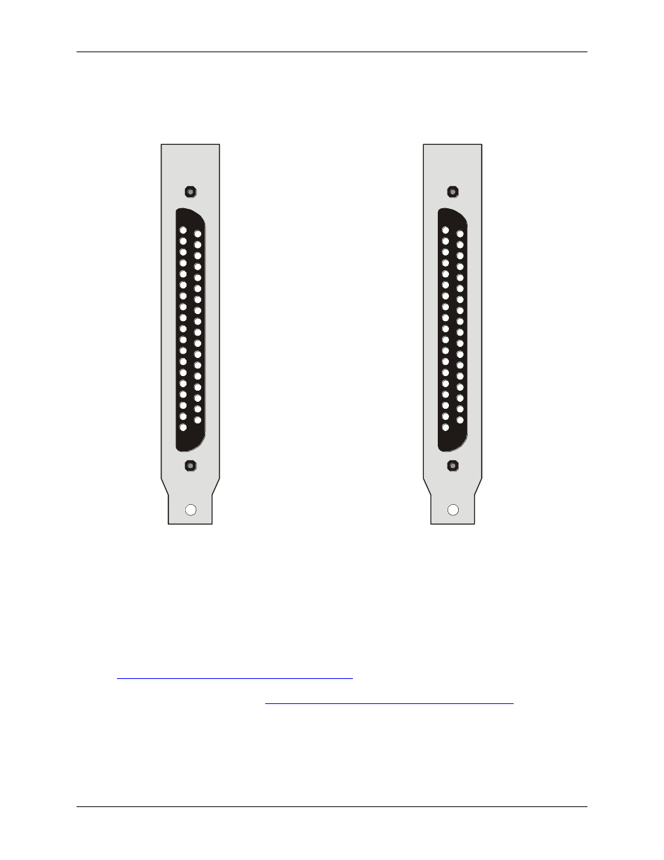
Pinout – main I/O connector
The CIO-DAS1401/12 I/O connector is a standard 37-pin male D connector that is accessible from the rear of
the computer through the expansion backplate.
LLGND 19
CH8 HI 18
CH9
17
CH10
16
CH11
15
CH12
14
CH13
13
CH14
12
CH15
11
10
9
-5V R O 8
DGND 7
DIN1 6
DIN3 5
D
1 4
DOUT3 3
CTR O 2
+5V PC B
1
HI
HI
HI
HI
HI
HI
HI
N/C
N/C
ef
ut
OUT
0
ut
US
37 CH0 HI
36 CH1 HI
35 CH2 HI
34 CH3 HI
33 CH4 HI
32 CH5 HI
31 CH6 HI
30 CH7 HI
29 LLGND
28 LLGND
27 N/C
26 SS&H OUT
25 DIN0 / Trigger
24 DIN2 / CTR0 Gate
23 DOUT0
22 DOUT 2
21 CTR0 Clock
20 CTR2 Out
Single-ended mode
LLGND 19
CH0 LO 18
CH1
17
CH
16
CH
15
CH
14
CH
13
CH
12
CH
11
10
9
-5V R O 8
DGND 7
DIN1 6
DIN3 5
D
1 4
DOUT3 3
CTR O 2
+5V PC B
1
LO
2 LO
LO
LO
LO
LO
LO
3
4
5
6
7
N/C
N/C
ef
ut
OUT
0
ut
US
37 CH0 HI
36 CH1 HI
35 CH2 HI
34 CH3 HI
33 CH4 HI
32 CH5 HI
31 CH6 HI
30 CH7 HI
29 LLGND
28 LLGND
27 N/C
26 SS&H OUT
25 DIN0 / Trigger
24 DIN2 / CTR0 Gate
23 DOUT0
22 DOUT 2
21 CTR0 Clock
20 CTR2 Out
Differential mode
Figure 7. I/O connector pin-out
Field wiring, signal termination, and conditioning
You can use the following cabling, screw termination, and signal conditioning products with the CIO-
DAS1401/12.
CIO-MINI37 – 37-pin screw terminal board. Details on this product are available on our web site at
CIO-SSH16 – 16-channel sample & hold front end board (four channels installed). Details on this product
are available from our web sit