Digital input / output, Interrupt input – Measurement Computing USB-4302 User Manual
Page 23
USB-4302 User's Guide
Specifications
23
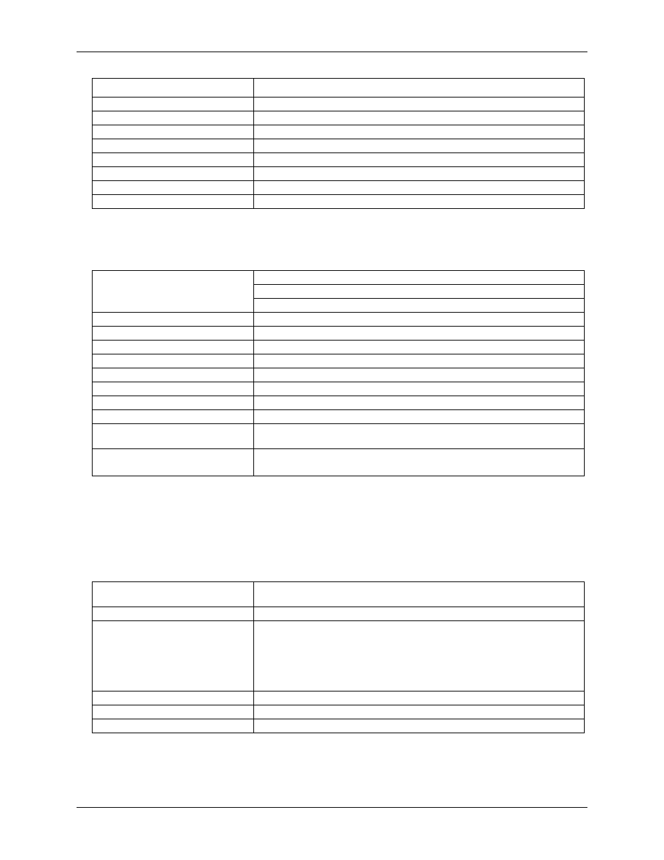
Parameter
Conditions
12 MHz crystal oscillator accuracy
±50 ppm
High pulse width (clock input)
25 ns min
Low pulse width (clock input)
25 ns min
Gate width
70 ns min
Input low voltage
-0.5 V min, 0.8V max
Input high voltage
2.0 V min, USB +5V power max
Output low voltage @ IIl = 4 mA
0.4 V max
Output high voltage @ IIH = 4 mA
2.4 V min
Digital input / output
Table 2. Digital I/O specifications
Digital type
Discrete, 5V/TTL compatible
Output: 74ACT373
Input:
74ACT373
Number of I/O
8 input, 8 output
Configuration
1 bank of 8 as output, 1 bank of 8 as input
Input high voltage
2.0 V min,5.5 V absolute max
Input low voltage
0.8 V max, –0.5 V absolute min
Output high voltage
3.3 volts min @ -24 mA (Vcc = 4.5 V)
Output low voltage
0.8 volts max @ 10 mA
Data transfer
Programmed I/O
Power-up / reset state
Digital outputs reset to TTL low
Digital I/O transfer rate
(system paced)
System dependent, 33 to 1000 port reads/writes or single bit reads/writes per
second.
Pull-up/pull-down configuration
User configurable for pull-up/-down through 47 kΩ resistor (Note 1).
All pins floating (default)
Note 1:
Pull-up and pull-down configurations are available using the DI CTL connector pin 21. The pull-
down configuration requires the DI CTL pin (pin 21) to be connected to a GND pin (pin 11). For
a pull-up configuration, the DI CTL pin should be connected to the +5V pin (pin 20).
Interrupt Input
Table 3. Interrupt specifications
Implementation
Interrupts the microcontroller operation on the device to execute one or more of
several firmware routines.
Interrupt characteristics
Rising edge (default) or falling edge triggered, user selectable
Firmware routines
Any or all of the following can be activated by the user:
Generate USB event notification
Latch digital inputs (Reading digital inputs returns most recently latched
value.)
Latch digital outputs (Most recently written digital output value is latched.)
Save counts on any/all of counters 1-5.
Event latency to PC
1-33 ms (4 ms typical)
Maximum event notification rate
33-1000 Hz (system dependent) (Note 2)
Interrupt latency for latch operations
100 µs maximum (80 µs typical)
Note 2:
The interrupt rate, when transferring information to the PC (event notification), is limited by the
USB to a theoretical limit of 1 kHz. Some systems may not be able to achieve this maximum rate
due to differences in USB controller implementation, traffic on the USB, or operating system
activity.