Oscillator output, Oscillator output (osc out), Ground (gnd) – Measurement Computing USB-4302 User Manual
Page 16: Internal sources, External sources
USB-4302 User's Guide
Functional Details
16
Oscillator output (OSC OUT)
The oscillator output connector (pin 30) outputs a configurable clock frequency. You can select the source of
the oscillator and also select dividers for the oscillator programmatically to set the output rate.
Ground (GND)
The ground (
GND
) connector (pin 11) provides a common ground for the digital and counter I/O connections.
Oscillator output
You can set the oscillator input programmatically to one of five internal frequency sources or one of 10 external
input pins. The oscillator output can be divided by any number from 1 to 16 before being output to the
OSC
OUT
pin.
Internal sources
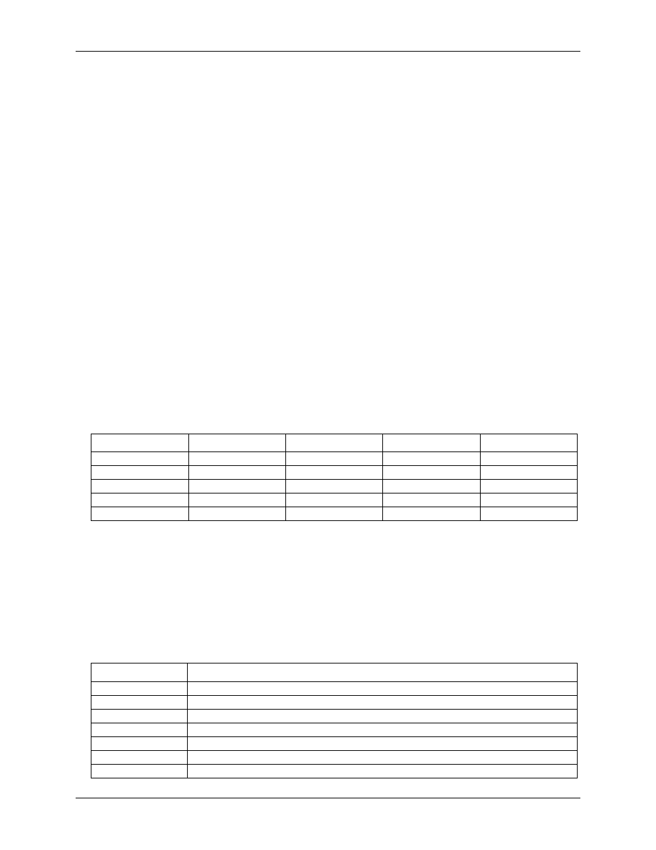
The base frequency for the internal frequency sources can be set through InstaCal to one of four different
frequencies — 1.0000 MHz, 1.6667 MHz, 3.3333 MHz, or 5.0000 MHz. This base frequency is used to
generate the five internal frequency sources — FREQ1 through FREQ5.
FREQ1 is the same as the base frequency, and each successive internal frequency following FREQ1 divides the
base frequency by another multiple of 10. For example, FREQ2 is the base frequency divided by 10, FREQ3 is
the base frequency divided by 100, and so on. This is illustrated in the following table.
Internal frequency values for different base frequencies
1.0000 MHz
1.6667 MHz
3.3333 MHz
5.0000 MHz
FREQ1
1.0000 MHz
1.6667 MHz
3.3333 MHz
5.0000 MHz
FREQ2
100.00 kHz
166.67 kHz
333.33 kHz
500.00 kHz
FREQ3
10.000 kHz
16.667 kHz
33.333 kHz
50.000 kHz
FREQ4
1.0000 kHz
1.6667 kHz
3.3333 kHz
5.0000 kHz
FREQ5
100.00 Hz
166.67 Hz
333.33 Hz
500.00 Hz
External sources
In addition to the five internal sources, the frequency source for the oscillator can be an input signal connected
to any of the five counter input pins (
CTR1IN
–
CTR5IN
) or any of the five gate pins (
CTR1GATE
–
CTR5GATE
). The input signal can have a maximum frequency of 20 MHz on the counter input pins, and a
maximum frequency of 7 MHz on the gate pins.
The table below applies to all internal and external sources.
Oscillator sources
Source
Description
CTRINPUT1
Counter 1 input pin
CTRINPUT2
Counter 2 input pin
CTRINPUT3
Counter 3 input pin
CTRINPUT4
Counter 4 input pin
CTRINPUT5
Counter 5 input pin
GATE1
Counter 1 gate pin
GATE2
Counter 2 gate pin