Specifications, Counter, Chapter 4 – Measurement Computing USB-4302 User Manual
Page 22
22
Chapter 4
Specifications
Typical for 25 °C unless otherwise specified.
Specifications in italic text are guaranteed by design.
Counter
Refer to the CTS9513-2 data sheet for complete 9513 specifications and operating modes. The CTS9513-2 data
sheet is available on our web site at
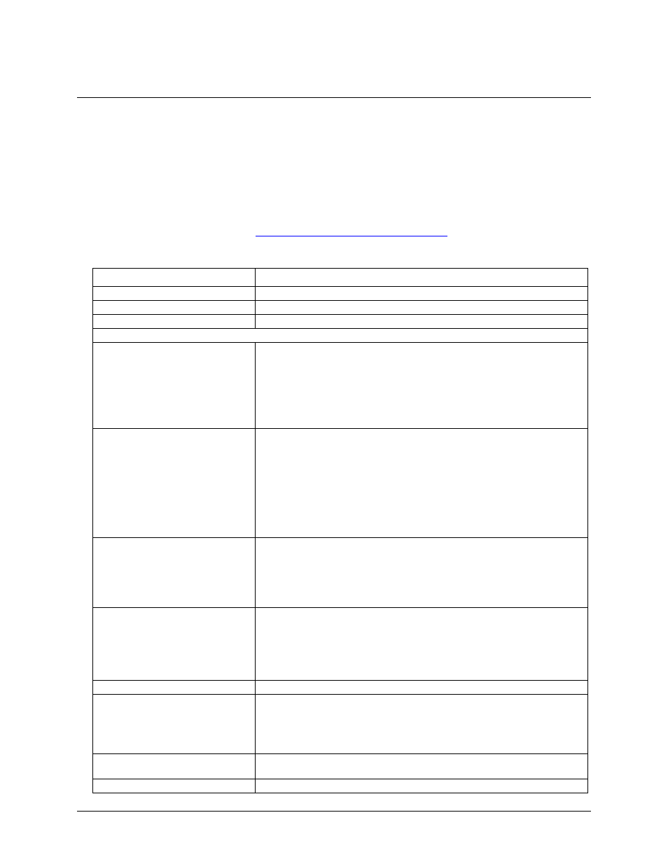
Table 1. Counter specifications
Parameter
Conditions
Counter type
9513
Configuration
One 9513 device. Five up/down counters, 16-bits each.
Compatibility
5V/TTL
The 9513 device is programmable for:
Clock source
Software selectable:
External:
Counter 1-5 clock inputs
Counter 1-5 gate inputs
Internal:
Terminal count of previous counter
Internal clock frequency scaler (default; divided by 1)
Gate
Software selectable source:
External:
Active high or low level or edge, counter 1 – 5 gate input
Active high level previous gate or next gate
All external gate signals (CTRxGATE) individually pulled up through 47 K
resistors to +5 V.
Internal:
Active high previous counter terminal count
No gating (default)
Output
Software selectable:
Always low (default)
High pulse on terminal count
Low pulse on terminal count
Toggle on terminal count
Inactive, high impedance at user connector counter # output.
Osc Out
Software selectable source:
Counter # input
Gate # input
Prescaled internal clock (default)
Software selectable divider:
Division by 1-16 (default = 16)
Clock input frequency
20 MHz max (50 nS min period)
Internal clock frequencies
(Generated from 12 MHz crystal
oscillator.)
Software selectable:
5.0000 MHz (default)
3.3333 MHz
1.6667 MHz
1.0000 MHz
Internal clock frequency prescaler
BCD scaling (Internal clock divided by 1, 10, 100, 1000 or 10000) or
Binary scaling (Internal clock divided by 1, 16, 256, 4096 or 65536)
Internal clock generator accuracy
±2 ppm