Signal connections, Counter input, gate, and output, Digital input and output (din, don) – Measurement Computing USB-4302 User Manual
Page 15
USB-4302 User's Guide
Functional Details
15
Signal connections
Counter input, gate, and output
The counter pins (
CTR1IN
to
CTR5IN
,
CTR1GATE
to
CTR5GATE
, and
CTR1OUT
to
CTR5OUT
) provide the
connections for the clock input signal and gate signal to each counter, and the output signal from each counter.
The clock, gate, and output sources are software-selectable. You can configure each counter to count up or
down.
Digital input and output (DIn, DOn)
You can connect up to eight digital input lines to pins
DI0
to
DI7
(pin 22 through 29), and up to eight digital
output lines to pins
DO0
to
DO7
(pin 3 through 10).
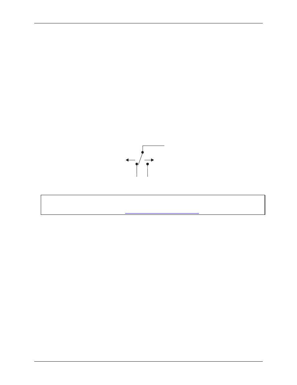
You can use the digital input pins to detect the state of any TTL level input. Refer to the schematic shown in
Figure 6. When the switch is set to the +5V input, DI7 reads TRUE (1). If you move the switch to GND, DI7
reads FALSE (0).
+5V
GND
DI
7
Figure 6. Schematic showing switch detection by digital channel DI7
For more information on digital signal connections
For more information on digital signal connections and digital I/O techniques, refer to the Guide to Signal
Connections (available on our web sit
Digital input pull-up/down configuration (DI CTL)
All digital input pins are floating by default. When inputs are floating, the state of unwired inputs is undefined
—they may read high or low. You can use the
DI CTL
connection (pin 21) to configure the inputs to read a high
or low value when they aren’t wired.
To pull up the digital input pins to +5 V — inputs read high when unwired — wire the
DI CTL
pin to the
+5V
pin (pin 20).
To pull down the digital input pins to ground — inputs read low when unwired — wire the
DI CTL
pin to
the
GND
pin (pin 11).
The
DI CTL
connection pulls the inputs to +5V or GND through a 47 k Ω resistor.
Interrupt input (INT)
You can configure the interrupt input connector (pin 1) with InstaCal to trigger off rising or falling edge inputs.
You can program this pin to perform the following tasks:
Send an event notification to the computer. The transfer rate is system-dependent.
Latch the digital inputs. With this option, the current value of the digital inputs (0 or 1) is read and stored.
The stored value is updated when an active edge occurs on this pin.
Latch the digital outputs. With this option, digital outputs are not set to the value written until an active
edge occurs on this pin.
Save the current value of a counter. You can configure this option for each counter individually.