Measurement Computing STLITE-PCI-8x User Manual
Page 6
2
2
COMPONENTS – STANDARD SYSTEM
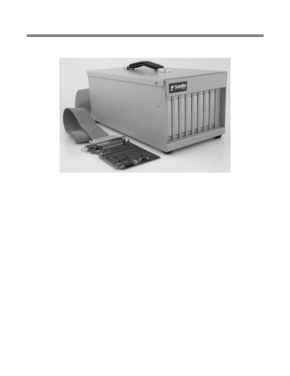
The STLITE-PCI-8T consists of the following major components (See Figure 2-1):
Figure 2-1. STLITE-PCI-8T Major Components
2.1
PCI EXPANSION MOTHERBOARD
The expansion motherboard is a printed circuit board mounted in the base of the enclosure. It receives bus
signals from the host computer. It places equivalent signals on the chassis secondary bus. There are eight
connectors (slots) on the secondary bus for installing boards. Up to four full-length and four half-length boards
can be installed in the eight slots.
A semiconductor sensor is provided on the motherboard for temperature monitoring. Its output is applied to an
A/D converter along with power supply voltages and a voltage signal related to DC-powered chassis cooling fan
current. Optionally, each of the eight card slot locations can have a temperature sensor mounted over it. The
sensors are mounted on a PCB strip mounted on the cabinet top cover. Analog signals from these sensors are
converted to digital data by a second A/D converter. The digital values, along with other monitor data, are sent
to the host computer over the expansion cable.
2.2
HOST PCI BRIDGE CARD:
STLITE-PCI-HOST
The Host Bridge card is a “half-size ” universal adapter card that can usually be installed in any open PCI slot in
the host computer. Certain systems may require the installation of the host card in a specific slot.
The Host Bridge card is connected via a three-foot shielded ribbon cable to an expansion bridge card in the PCI
Expansion Chassis.
2.3
POWER SUPPLY
The STLITE-PCI-8T incorporates a standard 250-Watt, ATX-type switching power supply in the cabinet. A
cooling fan is integrated in the power supply. All four output voltages are monitored to an accuracy of ±2%. The
power supply operates on either 115 or 230VAC (switch-selected).