3 fan-out configuration, 4 extended daisy chain configuration – Measurement Computing STLITE-PCI-8x User Manual
Page 11
7
The first expansion chassis also has a bridge. Its primary side is connected to Bus 1 and its downstream side is
attached to Bus 2 on the chassis motherboard.
If you were to insert another Host PCI Bridge card in an open slot in first expansion chassis, its primary side
would be attached to Bus 2 and its secondary side would be attached to a cable at Bus 3.
The bridge in the second expansion chassis will have its primary attached to Bus 3 and its secondary attached to
the motherboard’s Bus 4.
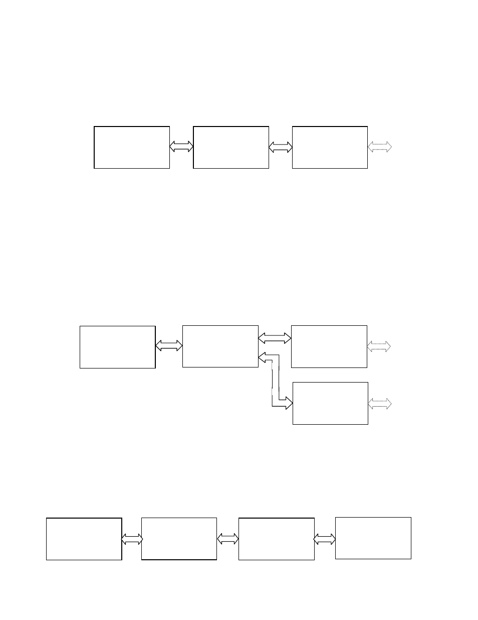
Figure 5-1. PCI Expansion Daisy Chaining
5.3
FAN-OUT CONFIGURATION
In this case, the Host Bridge card for a second PCI chassis is inserted in an open slot in the first [expansion]
chassis. The Host Bridge card for the first chassis is inserted in an open slot of the host computer as usual. The
first and second expansion chassis have bus level numbers identical with the daisy chain configuration described
above.
Adding a third expansion chassis to Bus 2 is the fan-out configuration (Figure 5-2).
NOTE: Although we have numbered the second chassis to extend from Bus 2 as “Bus 6”, logically, it is at the
same hierarchical level as Bus 4 since it is attached to Bus 2.
Figure 5-2. PCI-Expansion-Serial/Parallel Configuration
5.4
EXTENDED DAISY CHAIN CONFIGURATION
If , rather than attaching the third expansion chassis to Bus 2, we had attached it to Bus 4 (in the second
expansion chassis), then Bus 6 would be further downstream (logically speaking) than Bus 4 (Figure 5-3).
Figure 5-3. Extended Daisy Chain Configuration
Host
PCI Bridge
First Chassis
PCI Bridge
Second Chassis
PCI Bridge
Bus 0
Bus 1
Bus 3
Bus 2
Bus 4
Host
PCI Bridge
First Chassis
PCI Bridge
Second Chassis
PCI Bridge
Third Chassis
PCI Bridge
Bus 0
Bus 1
Bus 2
Bus 5
Bus 3
Bus 4
Bus 6
Host
PCI Bridge
First Chassis
PCI Bridge
Second Chassis
PCI Bridge
Third Chassis
PCI Bridge
Bus 0
Bus 1
Bus 2
Bus 5
Bus 3
Bus 4
Bus 6