Measurement Computing Serial488A User Manual
Page 28
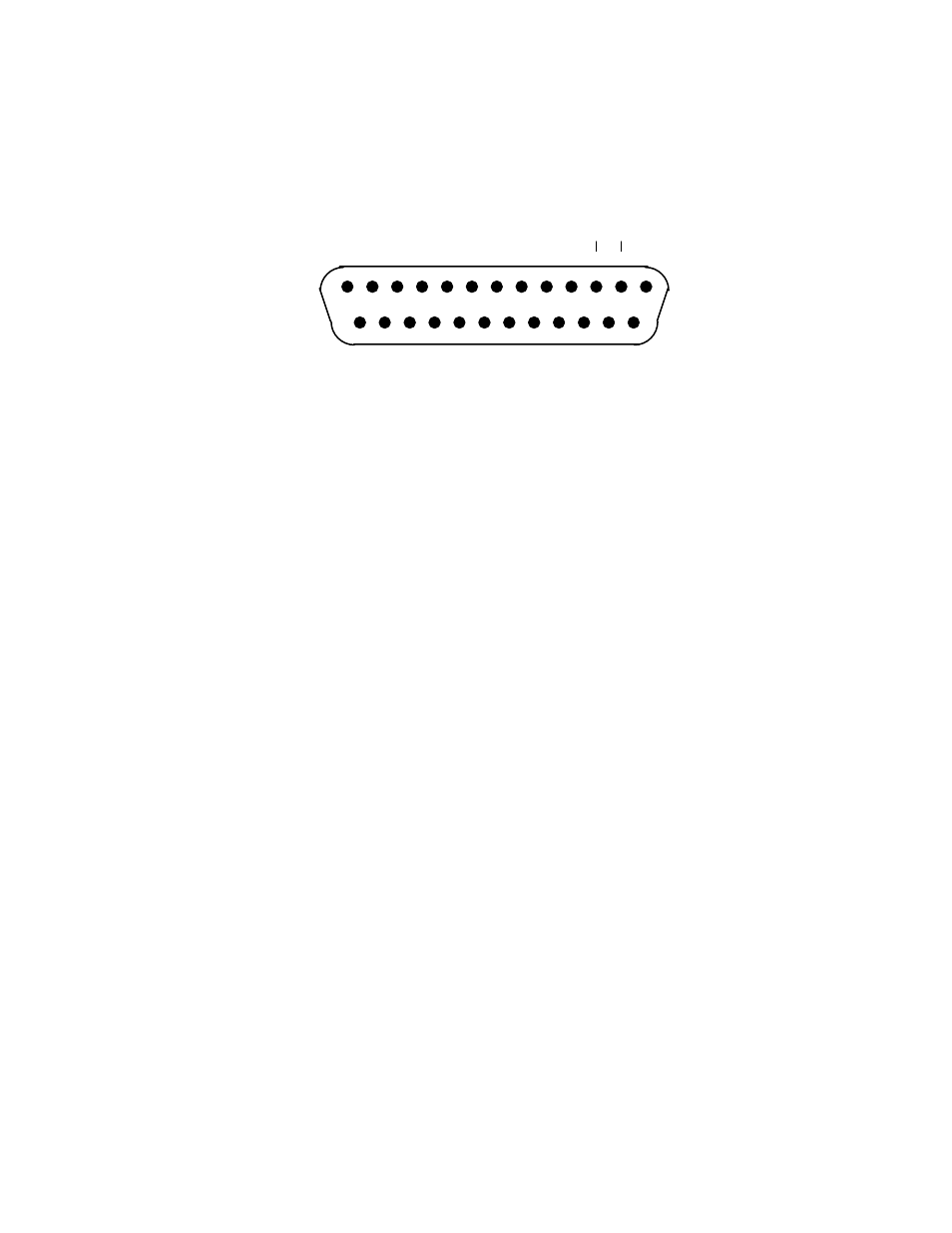
2.18
Rear View of the Serial488A's Serial Connector
-RXD
-TXD
CTS
RTS
+TXD
+RXD
+VTEST
+VTEST
GND
1
13
14
25
-RxD
Receive Data - Input - Pin 2
This pin accepts serial data sent by the RS-232 or RS-422 host.
The serial data is expected with the word length, baud rate, stop
bits and parity selected by the internal switches. The signal level is
low true.
-TxD
Transmit Data - Output - Pin 3
This pin transmits serial data to the RS-232 or RS-422 host. The
serial data is sent with the word length, baud rate, stop bits and
parity selected by the internal switches. The signal level is low
true.
CTS
Clear To Send - Input - Pin 4
The CTS input is used as a hardware handshake line to prevent the
Serial488A from transmitting serial data when the RS-232 host is
not ready to accept it. When RTS/CTS handshake is selected on
the internal switches, the Serial488A will not transmit data out -
TxD while this line is un-asserted (low). If the RS-232 host is not
capable of driving this line it can be connected to the Vtest output
(Pin 6) of the Serial488A. If Xon/Xoff handshake is selected, the
CTS line is not tested to determine if it can transmit data.