Led / button configuration – Measurement Computing WLS-TEMP User Manual
Page 31
WLS-TEMP Specifications
31
LED / button configuration
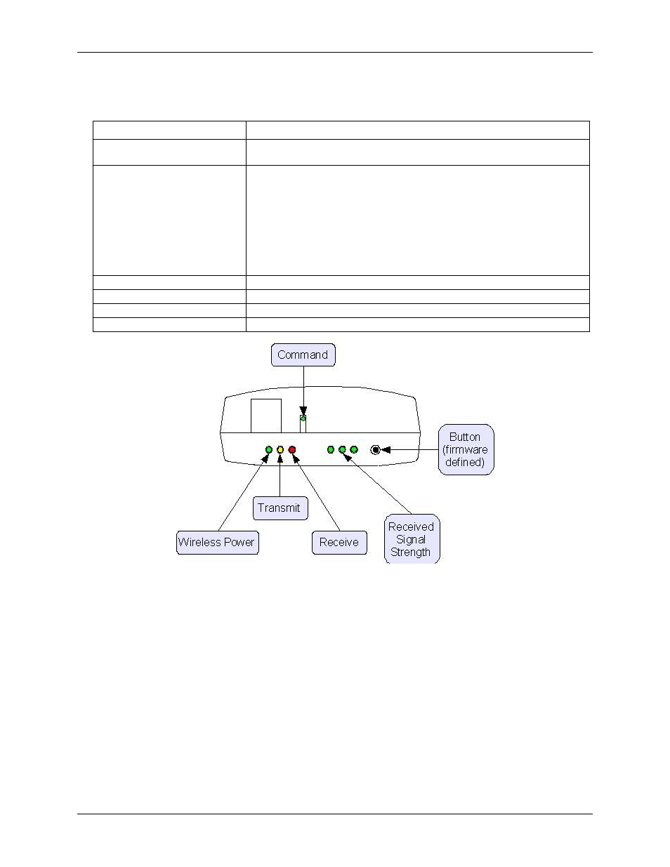
Table 21. LED configuration
Parameter
Specification
Command LED
Green LED – indicates a command was received by the device (either USB or
wireless)
Received Signal Strength Indicator
(RSSI) LEDs
Three green LED bar graph.
LEDs turn on when receiving a wireless message and stay on for approximately
1 second after the end of the message. The LEDs indicate the amount of fade
margin present in an active wireless link. Fade margin is defined as the difference
between the incoming signal strength and the receiver sensitivity of the device.
3 LEDs on: Very strong signal (>30 dB fade margin)
2 LEDs on: Strong signal (>20 dB fade margin)
1 LED on: Moderate signal (>10 dB fade margin)
0 LED on: Weak signal (<10 dB fade margin)
Wireless Power LED
Green LED: indicates that the internal RF module is powered.
Transmit LED
Yellow LED: indicates transmitting data over the wireless link.
Receive LED
Red LED: indicates receiving data over the wireless link.
Button
Firmware-defined; this revision executes an LED test.