Four-wire, two-sensor, Semiconductor sensor measurements, Wiring configuration – Measurement Computing WLS-TEMP User Manual
Page 17: Digital i/o connections
WLS-TEMP Specifications
17
Four-wire, two-sensor
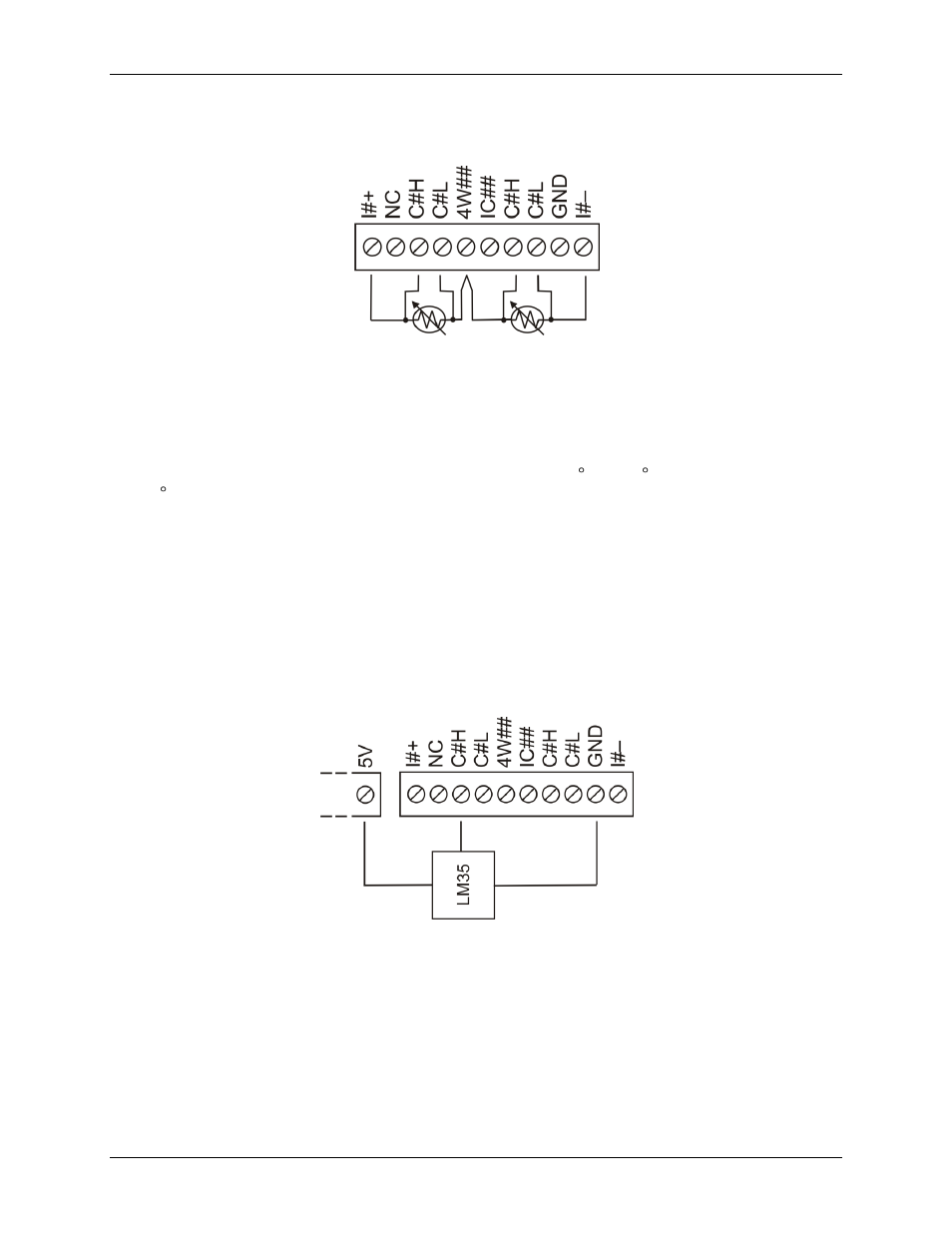
A four-wire, two-sensor measurement configuration is shown in Figure 8.
Figure 8. Four-wire, two RTD or thermistor sensors measurement configuration
When configured for four-wire, two sensor mode, both sensors must be connected to obtain proper
measurements.
Semiconductor sensor measurements
Semiconductor sensors are suitable over a range of approximately -40 C to 125 C, where an accuracy of
±2 C is adequate. The temperature measurement range of a semiconductor sensor is small when compared to
thermocouples and RTDs. However, semiconductor sensors are accurate, inexpensive, and easily interface with
other electronics for display and control.
The WLS-TEMP makes high-resolution measurements of semiconductor sensors and returns a 32-bit floating
point value in either a voltage or temperature.
Use InstaCal to select the sensor type (LM35, TMP35 or equivalent), and the sensor input channel that connects
to the sensor.
Wiring configuration
You can connect a semiconductor sensor to the WLS-TEMP using a single-ended configuration, as shown in
Figure 9. The WLS-TEMP also provides
+5V
and
GND
pins for powering the sensor.
Figure 9. Semiconductor sensor measurement configuration
Digital I/O connections
You can connect up to eight digital I/O lines to the screw terminals labeled
DIO0
to
DIO7
. You can configure
each digital bit for either input or output. All digital I/O lines are pulled up to +5V with a 47 K ohm resistor
(default). You can request the factory to configure the resistor for pull-down to ground if desired.
When you configure the digital bits for input, you can use the WLS-TEMP digital I/O terminals to detect the
state of any TTL-level input. Refer to the schematic shown in Figure 10. If you set the switch to the +5V input,
DIO0 reads TRUE (1). If you move the switch to GND, DIO0 reads FALSE (0).