Throughput rate to pc (usb or wireless), Digital input/output – Measurement Computing WLS-TEMP User Manual
Page 27
WLS-TEMP Specifications
27
Note 12:
Resistance values greater than 180 kΩ cannot be measured by the device in the thermistor mode.
The 180 kΩ resistance limit includes the total resistance across the current excitation (±Ix) pins, which
is the sum of the thermistor resistance and the lead resistances.
Note 13:
For accurate three wire compensation, the individual lead resistances connected to the ±Ix pins
must be of equal value.
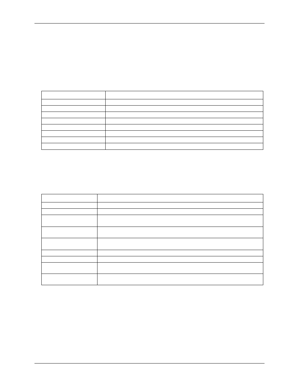
Throughput rate to PC (USB or wireless)
Table 9. Throughput rate specifications
Number of input channels
Maximum throughput
1
2 Samples/second
2
2 S/s on each channel, 4 S/s total
3
2 S/s on each channel, 6 S/s total
4
2 S/s on each channel, 8 S/s total
5
2 S/s on each channel, 10 S/s total
6
2 S/s on each channel, 12 S/s total
7
2 S/s on each channel, 14 S/s total
8
2 S/s on each channel, 16 S/s total
Note 14:
The analog inputs are configured to run continuously. Each channel is sampled twice per second.
The maximum latency between when a sample is acquired and the temperature data is provided by the
device is approximately 0.5 seconds
Digital input/output
Table 10. Digital input/output specifications
Parameter
Specification
Digital type
CMOS
Number of I/O
8 (DIO0 through DIO7)
Configuration
Independently configured for input or output.
Power on reset is input mode unless bit is configured for alarm.
Pull up/pull-down
configuration
All pins pulled up to +5 V via 47 kΩ resistors (default). Pull down to ground (GND) also
available.
Digital I/O transfer rate
(software paced)
Digital input: 50 port reads or single bit reads per second, typ
Digital output: 100 port writes or single bit writes per second, typ
Input high voltage
2.0 V min, 5.5 V absolute max
Input low voltage
0.8 V max, –0.5 V absolute min
Output low voltage
(IOL = 2.5 mA)
0.7 V max
Output high voltage
(IOH = –2.5 mA)
3.8 V min
Note 15:
All ground pins are common and are isolated from earth ground. If a connection is made to earth
ground when using digital I/O and conductive thermocouples, the thermocouples are no longer
isolated. In this case, thermocouples must not be connected to any conductive surfaces that may be
referenced to earth ground.