Usb-pdiso8/40 block diagram, Usb-pdiso8/40 block diagram -2 – Measurement Computing USB-PDISO8/40 User Manual
Page 7
USB-PDISO8/40 User's Guide
Introducing the USB-PDISO8/40
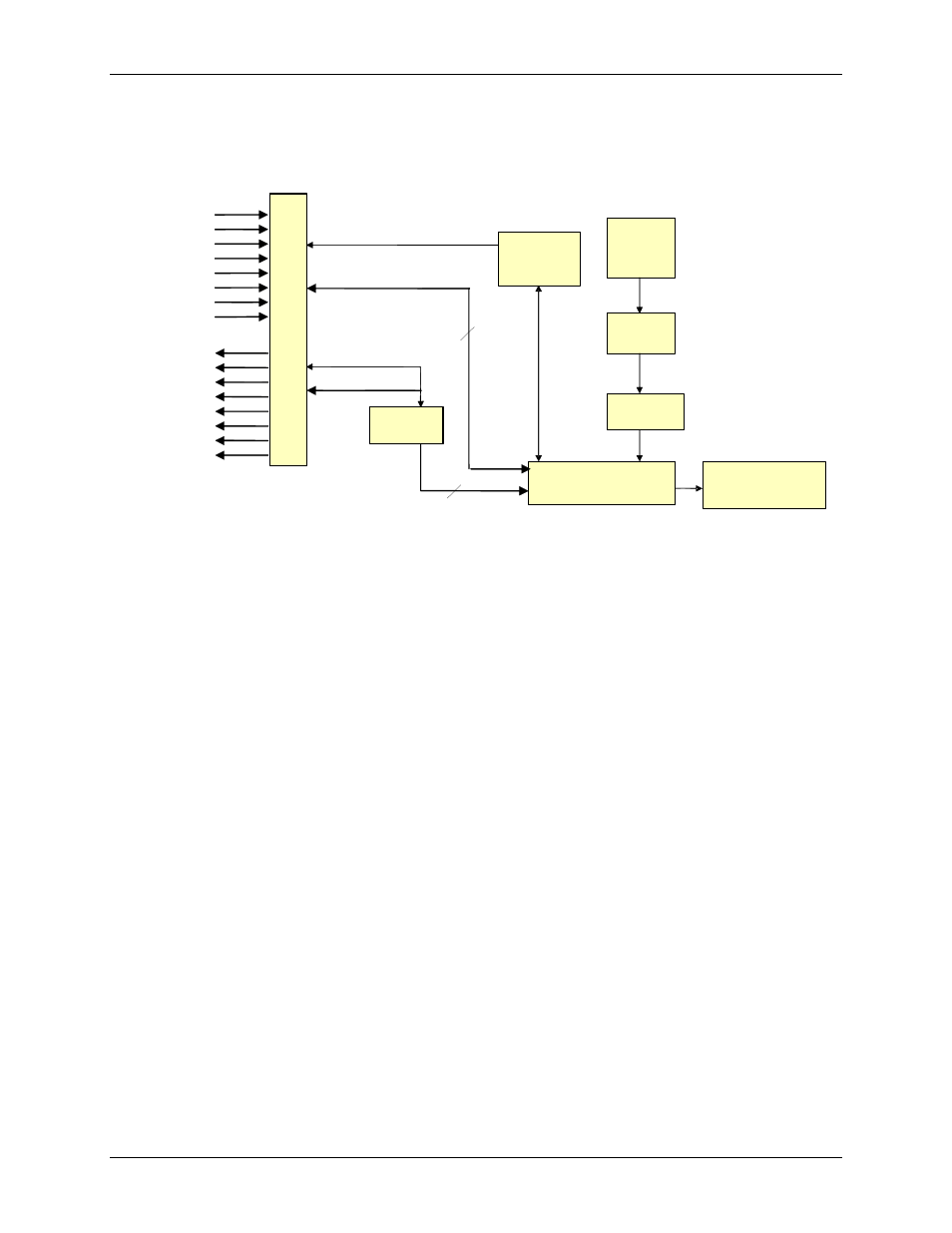
USB-PDISO8/40 block diagram
USB-PDISO8/40 functions are illustrated in the block diagram shown here.
USB
Controller
9 V
Nominal
External
Power
Power
Monitor
Power
Regulator
500 mA
USB 2.0
-
compliant
interface
Control
Registers
C
Hi
C
Lo
8
8
40-pin
I/O connector
Differential
isolated inputs
Form C
relay outputs
Relay
Driver
Figure 1-1. USB-PDISO8/40 functional block diagram
Connecting a USB-PDISO8/40 to your computer is easy
Installing a data acquisition device has never been easier.
The USB-PDISO8/40 relies upon the Microsoft Human Interface Device (HID) class drivers. The HID
class drivers ship with every copy of Windows that is designed to work with USB ports. We use the
Microsoft HID because it is a standard, and its performance delivers full control and maximizes data
transfer rates for your USB-PDISO8/40. No third-party device driver is required.
The USB-PDISO8/40 is plug-and-play. There are no jumpers to position, DIP switches to set, or
interrupts to configure.
You can connect the USB-PDISO8/40 before or after you install the software, and without powering
down your computer first. When you connect an HID to your system, your computer automatically
detects it and configures the necessary software. You can connect and power multiple HID peripherals
to your system using a USB hub.
You can connect your system to various devices using a standard four-wire cable. The USB connector
replaces the serial and parallel port connectors with one standardized plug and port combination.
Data can flow two ways between a computer and peripheral over USB connections.
Make sure that you have the latest Windows Updates installed for your USB driver, particularly "XP Hotfix
KB822603."
1-2